Experiment 2 - Microwave Optics
APPARATUS
- DC analog microammeter
- Microwave transmitter
- Microwave receiver
- Power supply
- Four-arm track with protractor and scale
- Ring stand with clamp
- Banana leads
- Triangular aluminum screens
- Flat aluminum screen
- Flat lucite screen
- Polarizer
- Single slit
- Double slits
- Assortment of materials: ceiling tiles, wood, metal plates
- Ruler
INTRODUCTION
In this experiment, you will test several optical aspects of electromagnetic waves such as polarization, reflection, and interference. The electromagnetic spectrum covers a wide range of frequencies. Visible light has a frequency of the order of 1014 Hz and wavelengths between 400 and 700 nm (1 nm = 10−9 m). Other well-known parts of the spectrum include radio waves (with frequencies near 106 Hz) and microwaves (with frequencies around 1010 Hz and wavelengths of a few centimeters). Microwaves can be generated easily and are particularly suited for laboratory investigations.
POLARIZATION, REFLECTION, AND ABSORPTION OF MICROWAVES
Electromagnetic waves consist of position-dependent and time-dependent electric and magnetic fields which are perpendicular to each other. These waves propagate in a direction perpendicular to both fields. In this experiment, we consider microwaves produced by a transmitter whose axis is vertical. The electric fields of these microwaves are therefore linearly polarized in the vertical plane and travel in the horizontal direction.
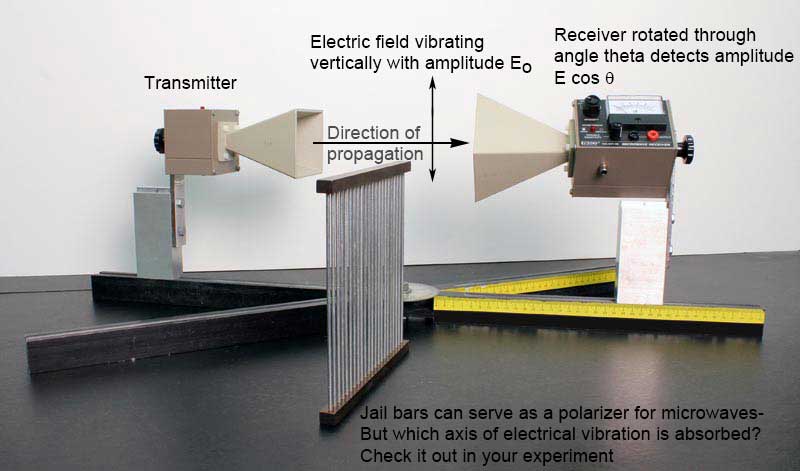
A receiver which detects such microwaves measures only the component of the incident electric field parallel to its axis. If the angle between the incident electric field (of amplitude \(E_0\) and the receiver axis is \(\theta\), then the parallel component of the field has amplitude \(E_0\cos\theta\), as shown in the figure above. Since the intensity of a wave is proportional to the square of its amplitude, the intensity \(I\) measured by the receiver is related to the intensity \(I_0\) of the incident wave by
\begin{eqnarray} I &=& I_0 \cos^2\theta. \label{eqn_Malus} \end{eqnarray}
Eq. \eqref{eqn_Malus} is known as Malus' Law and tells us how the intensity varies with angle between the transmitter and receiver.
A wave incident on a metallic surface will be reflected after striking the surface. The law of reflection states that the angle of reflection \(\theta_{\textrm{r}}\) is equal to the angle of incidence \(\theta_{\textrm{i}}\): \(\theta_{\textrm{r}} = \theta_{\textrm{i}}\). Note that both angles are measured with respect to the normal to the surface.
Microwaves which impinge upon an opaque material are either reflected by, transmitted through, or absorbed by the material. Let us denote the reflected, transmitted, absorbed, and total electric-field amplitudes by \(R\), \(T\), \(A\), and \(E\), respectively. The law of energy conservation tells us that the total energy of the incident microwaves is equal to the sum of the reflected, transmitted, and absorbed energies. Since energy is directly proportional to intensity and therefore proportional to the square of the electric-field amplitude, it follows that
\begin{eqnarray} E^2 &=& R^2 + T^2 + A^2 \end{eqnarray}
or
\begin{eqnarray} A^2 &=& E^2 - R^2 - T^2. \label{eqn_Absorbed} \end{eqnarray}
Thus, the percentage \(f_{\textrm{A}}\) of the incident microwave intensity absorbed by a material is
\begin{eqnarray} f_{\textrm{A}} &=& [(E^2 - R^2 - T^2) /E^2] \times 100\%. \label{eqn_fAbsorbed} \end{eqnarray}
INTERFERENCE
When two separate waves occupy the same region of space, they combine with each other. According to the superposition principle, the displacement of the resultant wave is equal to the sum of the displacements of the individual waves. If the crests of the individual waves coincide with each other, then the amplitude of the resultant wave is a maximum, and the waves are said to undergo constructive interference. On the other hand, if the crest of one wave coincides with the trough of the other wave, then the amplitude of the resultant wave is zero at all points, and the waves undergo destructive interference. Waves that interfere constructively “build each other up” and have a maximum intensity, while those that interfere destructively “cancel each other out” and have a minimum intensity.
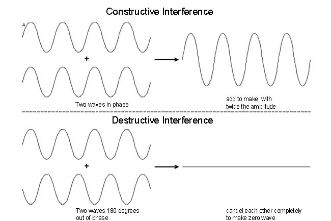
In this experiment you will build a device called a Michelson interferometer that splits a wave into two waves and then recombines the waves after they have traveled different distances. If the extra distance traveled by one of the two waves (called the path difference) is equal to an integral multiple of one wavelength (i.e., 0, \(\lambda\), \(2\lambda\), etc.), constructive interference results, and the combined waves be measured to have a large intensity, as shown in the figure above. Conversely, if the path difference is equal to an odd integral multiple of a half wavelength (i.e., \(\lambda/2\), \(3\lambda/2\), \(5\lambda/2\), etc.), destructive interference occurs, and the waves will cancel when they overlap and produce zero intensity.
INITIAL SETUP
You may find one of two types of microwave receiver/transitter setups at your station. Both of these setups use Gunn diodes to generate microwaves.
The most modern version, Pasco WA 9314B, is the easiest to use, and has a self-contained meter. Align the receiver horn facing the transmitter horn, and plug the transmitter in to turn it on. On the receiver, turn the intensity knob from “off” to “30”. Adjust the variable sensitivity knob for a full scale reading. You can increase the sensitivity later in the experimet if needed. When finished with the experiment, unplug the transmitter, and turn off the receiver.
The older Gunn diode unit uses a DC power supply for the transmitter, and a separate meter for the receiver. Be careful of the polarity from the power supply to the transmitter. The positive (red) connector of the power supply's output must be hooked to the positive (red) connector of the transmitter's input, or the diode will be destroyed. To adjust this device, place the receiver directly opposite the transmitter, and set the meter to minimum sensitivity. Turn on the power supply, and slowly increase the voltage until the diode begins to generate microwaves. You will notice that a further increase in voltage increases the output power until a plateau voltage is reached. After this point, an increase in voltage does not increase the output power. The transmitter should be operated at the beginning of this plateau. Never exceed 15 Volts DC, as doing so would destroy the Gunn diode.
The microwave receiver consists of a crystal diode which produces a current when aligned parallel to the electric field of the incident microwaves. The diode is not sensitive to microwaves whose electric field is perpendicular to its axis. The current from the diode is read by the horn. Be careful of the polarity between the receiver and the meter. The positive (red) connector of the receiver's output must be hooked to the positive (red) connector of the meter's input, or the meter movement may be destroyed. Never connect the receiver to the power supply, as this will destroy the diode instantly.
PROCEDURE
-
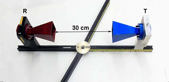
The microwaves emerging from the transmitter are linearly polarized in the vertical plane, and the receiver is sensitive only to the electric-field component parallel to its axis. Begin by recording the wavelength of the microwaves produced by the transmitter. Stand the transmitter and receiver vertically, with the two horns facing and approximately 30 cm apart from each other, as shown below.
-
Connect the receiver to the meter, and align the transmitter and receiver horns such that the meter reading is a maximum. Adjust the sensitivity of the meter to read a convenient value (e.g., 100) at the maximum, and take this orientation of the receiver to be \(\theta\) = 0° in Eq. \eqref{eqn_Malus}. Rotate the receiver in 5° increments, and record its reading for angles between 0° and 90° in the “Data” section. Since the meter measures the relative electric-field amplitude of the microwaves, you must square all readings to obtain the relative intensity \(I\). Plot the experimental values of \(I\) as a function of \(\theta\).
-
Using Eq. \eqref{eqn_Malus}, plot the theoretical values of \(I\) as a function of \(\theta\). Comment on the extent to which your data agrees with or differs from Malus' Law.
-
Return the receiver to its vertical position. Place the polarization grid between the transmitter and receiver, as shown below.
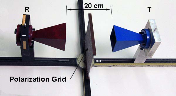
Rotate the polarization grid until it blocks all incoming microwaves, and note the orientation of the bars with respect to the incident electric field (i.e., either parallel or perpendicular). Explain what is happening. (This is not obvious. It has nothing to do with waves “squeezing between the bars”, but has much to do with the fact that the bars are conductors. You may wish to refer to your data in step 6 for a hint.)
-
The reflection of microwaves by a full reflector (i.e., an aluminum plate) is measured with the setup shown below.
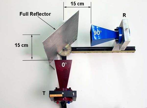
Place the transmitter approximately 15 cm from the reflector at an angle of incidence \(\theta_{\textrm{i}}\) = 30° (as measured by the protractor on the four-armed base). Vary the angle of the receiver (as measured by the protractor) until the meter reading is a maximum. Record this angle of reflection \(\theta_{\textrm{r}}\). Repeat the procedure for angles of incidence of 45° and 60°, measure the corresponding angles of reflection, and check the validity of the law of reflection.
-
Arrange the setup for absorption and reflection as shown below.
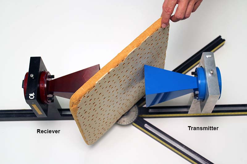
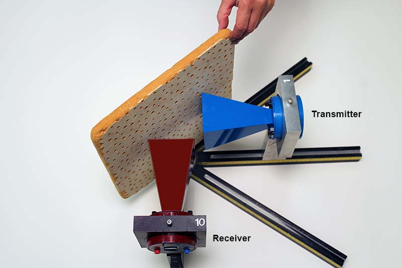
Place the transmitter and receiver horns facing and approximately 10 cm from each other. Adjust the sensitivity of the meter to read a convenient value (e.g., 100). This is the maximum electric-field amplitude (\(E\,\)) detected by the receiver. Place at least four different materials (two metal, one nonmetal, and lucite) at an angle of 45° with respect to the beam, and record the transmitted amplitude (\(T\,\)) for each material. Rotate the receiver so that it is at a right angle to the transmitter (as measured by the protractor), place the materials at an angle of 45° with respect to the beam, and record the reflected amplitude (\(R\,\)) for each material. Using Eq. \eqref{eqn_fAbsorbed}, calculate the percentage \(f_{\textrm{A}}\) of the incident microwave intensity absorbed by each material.
-
The wavelength \(\lambda\) of the microwaves can be measured with the Michelson interferometer shown below. (An interferometer is a device that can be used to measure lengths or changes in length with great accuracy by means of interference effects.)
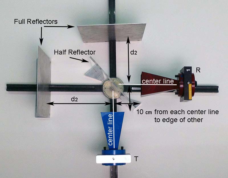
The transmitter and receiver horns should each be approximately 10 cm from the center of the track. Place the two full (aluminum) reflectors at right angles to each other (as measured by the protractor) and at distances \(d_1\) and \(d_2\) from the center of the track. Place the half (lucite) reflector at an angle of 45° with respect to the incident beam. Adjust \(d_1\) (the position of the full reflector opposite the receiver) until the receiver reading is a minimum. Next, adjust \(d_1\) (the position of the full reflector opposite the transmitter) until the receiver reading is a minimum. Then vary \(d_1\) between 15 cm and 40 cm, and record at least 15 values of \(d_1\) for which the receiver output is a minimum. Knowing that the distance between adjacent minima is \(\lambda/2\), calculate \(\lambda\) for each pair of adjacent minima, and determine the average wavelength. Compare this value with the wavelength recorded in step 1.
DATA
-
Wavelength of microwaves =
-
Amplitude at \(\theta\) = 0° =
Amplitude at \(\theta\) = 5° =
Amplitude at \(\theta\) = 10° =
Amplitude at \(\theta\) = 15° =
Amplitude at \(\theta\) = 20° =
Amplitude at \(\theta\) = 25° =
Amplitude at \(\theta\) = 30° =
Amplitude at \(\theta\) = 35° =
Amplitude at \(\theta\) = 40° =
Amplitude at \(\theta\) = 45° =
Amplitude at \(\theta\) = 50° =
Amplitude at \(\theta\) = 55° =
Amplitude at \(\theta\) = 60° =
Amplitude at \(\theta\) = 65° =
Amplitude at \(\theta\) = 70° =
Amplitude at \(\theta\) = 75° =
Amplitude at \(\theta\) = 80° =
Amplitude at \(\theta\) = 85° =
Amplitude at \(\theta\) = 90° =
Intensity at \(\theta\) = 0° =
Intensity at \(\theta\) = 5° =
Intensity at \(\theta\) = 10° =
Intensity at \(\theta\) = 15° =
Intensity at \(\theta\) = 20° =
Intensity at \(\theta\) = 25° =
Intensity at \(\theta\) = 30° =
Intensity at \(\theta\) = 35° =
Intensity at \(\theta\) = 40° =
Intensity at \(\theta\) = 45° =
Intensity at \(\theta\) = 50° =
Intensity at \(\theta\) = 55° =
Intensity at \(\theta\) = 60° =
Intensity at \(\theta\) = 65° =
Intensity at \(\theta\) = 70° =
Intensity at \(\theta\) = 75° =
Intensity at \(\theta\) = 80° =
Intensity at \(\theta\) = 85° =
Intensity at \(\theta\) = 90° =
Plot the experimental graph of \(I\) as a function of \(\theta\) using one sheet of graph paper at the end of this workbook. Remember to label the axes and title the graph.
-
Plot the theoretical graph of \(I\) as a function of \(\theta\) using the same sheet of graph paper. Remember to label the axes and title the graph.
-
Which orientation of the bars blocks all incoming microwaves? Why?
-
Angle of reflection for \(\theta_{\textrm{i}}\) = 30° =
Angle of reflection for \(\theta_{\textrm{i}}\) = 45° =
Angle of reflection for \(\theta_{\textrm{i}}\) = 60° =
-
Maximum electric-field amplitude =
Material 1 =
Material 2 =
Material 3 =
Material 4 =
Transmitted amplitude for material 1 =
Transmitted amplitude for material 2 =
Transmitted amplitude for material 3 =
Transmitted amplitude for material 4 =
Reflected amplitude for material 1 =
Reflected amplitude for material 2 =
Reflected amplitude for material 3 =
Reflected amplitude for material 4 =
Percentage of microwave intensity absorbed by material 1 =
Percentage of microwave intensity absorbed by material 2 =
Percentage of microwave intensity absorbed by material 3 =
Percentage of microwave intensity absorbed by material 4 =
-
Positions at which receiver output is a minimum =
Wavelength for each pair of adjacent minima =
Average wavelength =
Percentage difference between average wavelength and value recorded in step 1 =
