
Instructional Resource Lab
Experiment 3 - Geometrical Optics
APPARATUS
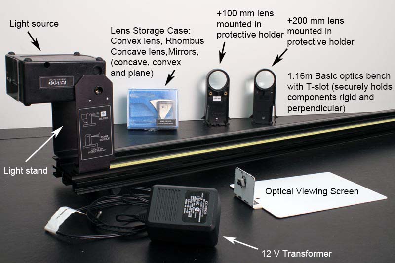
This lab consists of many short optics experiments. Check over the many pieces of equipment carefully:
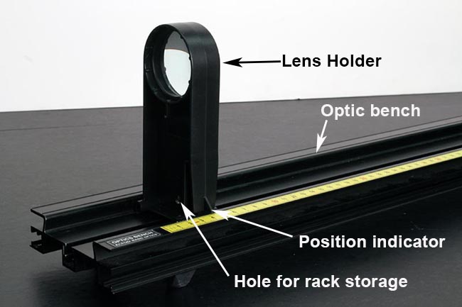
Shown in the picture below:
- Optical bench with screen at one end and ray-box bracket at the other end
- Ray box with 12-V transformer
- Lens storage case with four items inside
- Four lens holders with +200 mm, +100 mm, +25 mm, and −25 mm lenses. (Two of these lenses are shown in the diagram below.)
Not shown in the picture above:
- Protractor and ruler
- Diverging lens with unknown focal length
- Card with fine print
- Graph paper
- Tape in room
If anything is missing, notify your TA. At the end of the lab, you must put everything back in order again, and your TA will check for missing pieces.
REFLECTION AND REFRACTION
When a beam of light enters a transparent material such as glass or water, its overall speed through the material is slowed from \(c\) (3 × 10⁸ m/s) in vacuum by a factor of \(n\) (> 1):
\begin{eqnarray} \textrm{(speed in material)} &=& c/n. \end{eqnarray}
The parameter \(n\) is called the index of refraction, and is generally between 1 and 2 for most transparent materials. Even air has a refractive index slightly greater than 1.
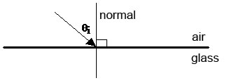
Consider a light beam impinging on the boundary between two transparent materials (e.g., a beam passing from air into glass). By convention, the angle of incidence \(\theta_{\textrm{i}}\) is measured with respect to the normal to the boundary.
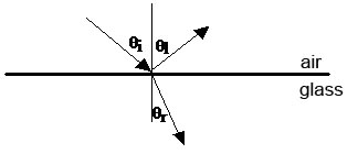
In general, the beam will be partially reflected from the boundary at an angle \(\theta_{\textrm{l}}\) with respect to the normal and partially refracted into the material at an angle \(\theta_{\textrm{r}}\) with respect to the normal.
Fermat's Principle, which states that light travels along the path requiring the least time, can be used to derive the laws of reflection and refraction.
Law of Reflection:
\begin{eqnarray} \theta_{\textrm{l}} &=& \theta_{\textrm{i}}. \end{eqnarray}
The angle of reflection \(\theta_{\textrm{l}}\) is equal to the angle of incidence \(\theta_{\textrm{i}}\).
Law of Refraction:
\begin{eqnarray} n_1\sin\theta_{\textrm{i}} &=& n_2\sin\theta_{\textrm{r}}. \end{eqnarray}
This is also called Snell's Law, where \(n_1\) is the refractive index of the material from which light is incident (air in this case), and \(n_2\) is the refractive index of the material to which light is refracted (glass in this case).
THIN LENSES
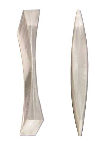
A thin lens is one whose thickness is small compared to the other characteristic distances (e.g., its focal length). The surfaces of the lens can be either convex or concave, or one surface could be planar. Because of the refractive properties of its surfaces, the lens will either converge or diverge rays that pass through it. A converging lens (such as the first plano-convex lens below) is thicker at its center than at its edges. A diverging lens (such as the second concave meniscus lens below) is thinner at its center than at its edges.
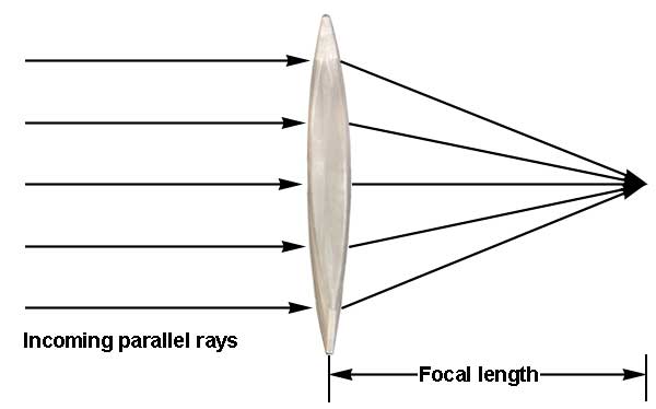
If parallel rays (say, from a distant source) pass through the lens, then a converging lens will bring the rays to an approximate focus at some point behind the lens. The distance between the lens and the focus of parallel rays is called the focal length of the lens.
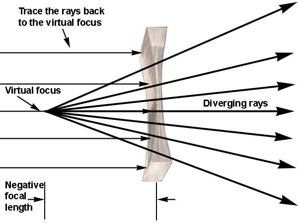
If the lens is diverging, then parallel rays passing though the lens will spread out, appearing to come from some point in front of the lens. This point is called the virtual focus, and the negative of the distance between the lens and the virtual focus is equal the focal length of the diverging lens.
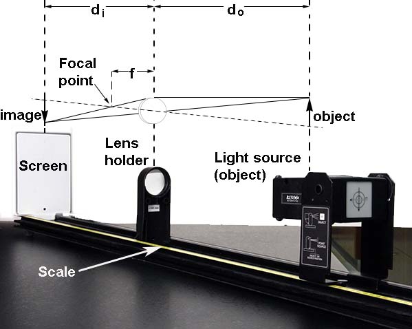
If an object (say, a lighted upright arrow) is placed near a lens, then the lens will form an image of the arrow at a specific distance from the lens. Let's call the distance between the lens and the object \(d_{\textrm{o}}\), and the distance between the lens and the image \(d_{\textrm{i}}\). Applying the Law of Refraction to the thin lens results in the thin-lens equation, which relates these quantities to the focal length \(f\):
\begin{eqnarray} 1/f &=& 1/d_{\textrm{o}} + 1/d_{\textrm{i}}. \end{eqnarray}
Recall that \(f\) can be positive or negative, depending on whether the lens is converging or diverging, respectively. Once the object distance \(d_{\textrm{o}}\) is chosen, the image distance \(d_{\textrm{i}}\) may turn out to be positive or negative. If \(d_{\textrm{i}}\) is positive, then a real image is formed. A real image focuses on a screen located a distance \(d_{\textrm{i}}\) behind the lens. If \(d_{\textrm{i}}\) is negative, then a virtual image is formed. A virtual image does not focus anywhere, but light emerges from the lens as though it came from an image located a distance \(\mid d_{\textrm{i}} \mid\) in front of the lens. You can see the virtual image by looking back through the lens toward the object. Such an image can be observed when you are looking through a diverging lens. These virtual images looks smaller and more distant.
CURVED MIRRORS
A curved mirror can also converge or diverge light rays that impinge on it. A converging mirror is concave, while a diverging mirror is convex. The mirror equation is identical to the thin-lens equation:
\begin{eqnarray} 1/f &=& 1/d_{\textrm{o}} + 1/d_{\textrm{i}}. \end{eqnarray}
We just need to remember that a real image with a positive image distance \(d_{\textrm{i}}\) will be formed on the same side of the mirror as the incident rays from the object, while a virtual image with a negative image distance \(d_{\textrm{i}}\) will be formed behind the mirror.
PROCEDURE PART 1: REFRACTION AND TOTAL INTERNAL REFLECTION
-
Place the ray box, label side up, on a white sheet of paper on the table. Plug in its transformer. Adjust the box so that one white ray is showing.
-
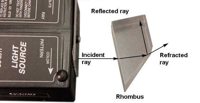
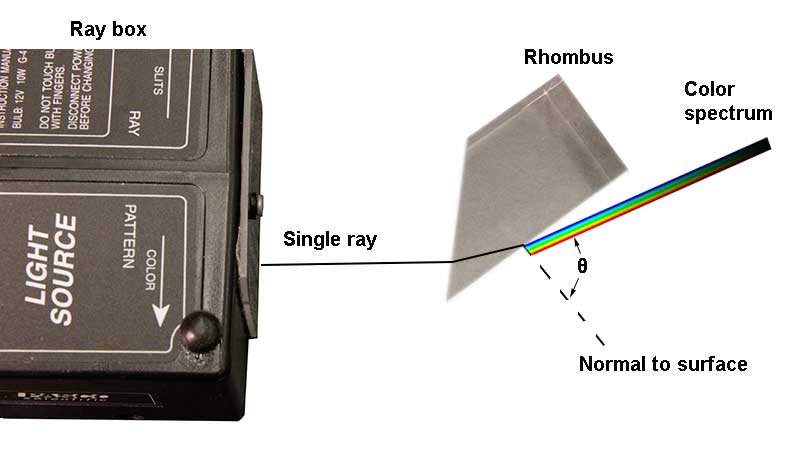
Position the rhombus as shown in the figure. The triangular end of the rhombus is used as a prism in this experiment. Keep the ray near the point of the rhombus for the maximum transmission of light. Notice that a refracted ray emerges from the second surface, and a reflected ray continues in the acrylic of the rhombus.
-
The incident ray is bent once as it enters the acrylic of the rhombus, and again as it exits the rhombus. Vary the angle of incidence. Does the exiting ray bend toward or away from the normal? (Physicists and opticians measure the angles of the rays with respect to the normal, a line perpendicular to the surface.)
Does the exiting ray bend toward or away from the normal?
-
Pick an angle of incidence for which the exiting ray is well bent, and trace neatly the internal and exiting rays on the top half of the paper underneath. Also trace the rhombus-air interfaces, clearly marking the side corresponding to the rhombus and that corresponding to air. You can simply mark the ends of the rays and use a ruler to extend the rays. Use the protractor to construct the normal to the interface and measure the angles of the two rays with respect to the normal. With these angles, use Snell's Law to find the refractive index of the acrylic of the rhombus. (Use \(n=1\) for air.)
Angle of ray in acrylic =
Angle of ray in air =
Refractive index (\(n\)) of acrylic =
Show your calculation of \(n\) below:
-
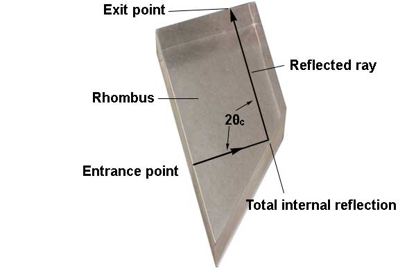
Total internal reflection: Rotate the rhombus until the exiting ray travels parallel to the surface (separating into colors), and then rotate the rhombus slightly farther. Now there is no refracted ray; the light is totally internally reflected from the inner surface. Total internal reflection occurs only beyond a certain “critical angle” \(\theta_{\textrm{c}}\), the angle at which the exiting refracted ray travels parallel to the surface. Rotate the rhombus again, and notice how the reflected ray becomes brighter as you approach and reach the critical angle. When there is both a refracted ray and a reflected ray, the incident light energy is divided between these rays. However, when there is no refracted ray, all of the incident energy goes into the reflected ray (minus any absorption losses in the acrylic).
Adjust the rhombus exactly to the critical angle, and trace neatly the ray in the acrylic and the refracting surface on the bottom half of the paper. Construct the normal to the surface, and measure the critical angle of the ray. (Again, all angles are measured with respect to the normal.) According to the textbook, the sine of the critical angle is
\begin{eqnarray} \sin\theta_{\textrm{c}} &=& 1/n. \end{eqnarray}
Calculate \(n\) from this relation, and compare it to the \(n\) determined in step 4.
Measured critical angle \(\theta_{\textrm{c}}\) =
Refractive index (\(n\)) determined from critical angle =
Refractive index (\(n\)) determined from Snell's Law (copy from step 4) =
-
Adjust the rhombus until the angle of the exiting ray is as large as possible (but less than the critical angle) and still clearly visible, and the exiting ray separates into colors. This phenomenon is called dispersion and illustrates the refraction of different colors at various angles. Which color is refracted at the largest angle, and which color is refracted at the smallest angle?
Color refracted at largest angle =
Color refracted at smallest angle =
PROCEDURE PART 2: REFLECTION
-
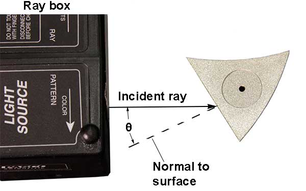
As in the preceding section, the ray box should be on a white sheet of paper, label side up, with one white ray showing.
-
Place the triangular-shaped mirror piece on the paper, and position the plane surface so that both the incident and reflected rays are clearly seen.
-
By turning the mirror piece, vary the angle of incidence while observing how the angle of reflection changes. What is the relation between the angle of incidence and the angle of reflection?
Relation:
PROCEDURE PART 3: CONVERGENCE AND DIVERGENCE OF RAYS
-
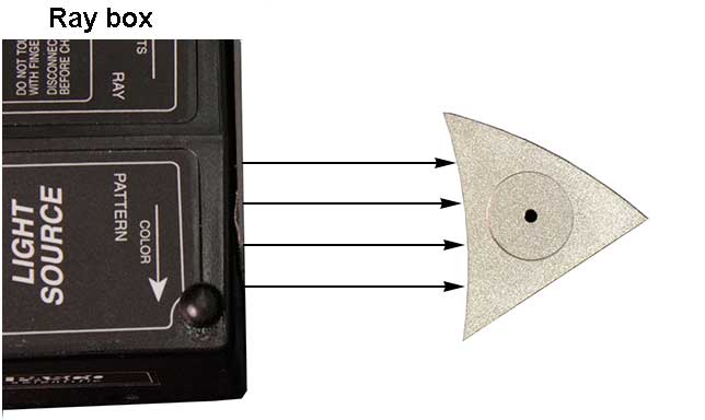
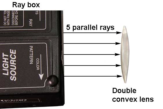
Either a mirror or a lens can converge or diverge parallel rays. The triangular mirror piece has a concave and a convex side, and there is a section of a double convex lens and a double concave lens. Adjust the ray box so that it makes five parallel white rays.
-
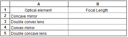
The concave mirror and the double convex lens (shown above) both converge the parallel rays to an approximate focal point. The distance between the lens or mirror surface and the focal point of parallel rays is the focal length of the mirror or lens. Measure the focal lengths of the concave mirror and convex lens in centimeters, and enter them in the table below.
-
The convex mirror and the double concave lens both diverge the parallel rays. They have negative focal lengths, and the magnitude of the focal length is equal to the distance between the optical element and the point from which the rays appear to diverge. Using the convex mirror and the double concave lens (one at a time), sketch the mirror or lens surface in position, and trace the diverging rays on the white paper. Remove the mirror or lens, and continue tracing the rays back to the virtual focus using a ruler. Enter the (negative) focal lengths (in centimeters) of these optical elements in the table above.
PROCEDURE PART 4: IMAGE FORMATION AND FOCAL LENGTH OF A LENS
-
Place the 200-mm lens and the screen on the optical-bench track. Do not put the light source on yet.
-
Focus a distant light source (such as a window, the trees outside the window, or a light at the other end of the room) on the screen. A distant source is effectively at infinity, the rays from the source are parallel, and the lens converges the rays to an image at the focal point. Measure the distance between the lens and the screen, and compare this distance to the stated focal length. (You may read positions off the optical bench scale and subtract them to find distances.)
Notice that the image is inverted. This is similar to how your eye lens forms an inverted image of the outside world on your retina.
-
Now mount the light source with the circles and arrows side facing the lens and screen. You need to unplug the power cord of the light box, and then replug it when the box is mounted. (There are two ways to mount the light source in the bracket. Notice the two holes in the bracket for the detent buttons on either side. For one way, the offset of the bracket arm below permits reading the position of the light source directly from the scale; for the other way, you would need to correct for the setback of the light source.)
-
Adjust the position of the lens until the image of the light source is focused sharply on the screen. Read the distances \(d_{\textrm{o}}\) and \(d_{\textrm{i}}\) in the figure off the scale, and calculate the focal length of the lens from the thin-lens equation:
\begin{eqnarray} 1/f &=& 1/d_{\textrm{o}} + 1/d_{\textrm{i}}. \end{eqnarray}
Enter the data below:
\(d_{\textrm{o}}\) =
\(d_{\textrm{i}}\) =
\(1/f\) =
\(f\) (calculated) =
\(f\) (theoretical) =
Here \(f\) (calculated) is the value obtained from the thin-lens equation, and \(f\) (theoretical) is the value read off the lens. These two focal lengths should, of course, agree approximately.
PROCEDURE PART 5: TWO-LENS SYSTEMS
-
Place the light source at 110 cm and the screen at 60 cm on the optical-bench scale. Place the +100 mm lens between the light source and the screen. You will find it possible to obtain a sharp image on the screen with the lens at about 72 cm. Is the image upright or inverted? Adjust for the exact focus, measure the object and image distances (read positions off the scale and subtract them), and compare the theoretical focal length with that obtained from the thin-lens equation.
\(d_{\textrm{o}}\) =
\(d_{\textrm{i}}\) =
\(1/f\) =
\(f\) (calculated) =
\(f\) (theoretical) =
Is the image upright or inverted?
-
The image formed at 60 cm can serve as the object for a second lens. Move the screen back, and place the +25 mm lens at 55 cm on the scale. Where does the image focus? Is it upright or inverted? Measure the object and image distances for the +25 mm lens, and compare the theoretical focal length with that obtained from the thin-lens equation.
\(d_{\textrm{o}}\) =
\(d_{\textrm{i}}\) =
\(1/f\) =
\(f\) (calculated) =
\(f\) (theoretical) =
Is the image upright or inverted?
-
If a second lens is placed inside the focal point of the first lens, the image of the first lens serves as a virtual object for the second lens. Place the +200 mm lens at 68 cm on the scale. The object distance is the negative of the distance between the lens and the point at which the image would have formed: namely, −8.0 cm if the first image were at 60 cm and the second lens were at 68 cm. Where does the image focus now? Is it upright or inverted? Compare the theoretical focal length with that obtained from the thin-lens equation.
\(d_{\textrm{o}}\) =
\(d_{\textrm{i}}\) =
\(1/f\) =
\(f\) (calculated) =
\(f\) (theoretical) =
Is the image upright or inverted?
-
Repeat step 3, placing the diverging −25 mm lens at 68 cm on the scale. This strongly diverging lens bends the rays from the +100 mm lens outward so that they diverge and never come to a focus beyond the lens. Instead, look through the two lenses back to the source. You will see the virtual image at a distance. Is it upright or inverted? Calculate the image distance of the −25 mm lens with its virtual object. The result comes out negative. Look through the lenses again. Does the image distance seem reasonable?
\(d_{\textrm{o}}\) =
\(d_{\textrm{i}}\) =
Does image distance seem reasonable?
Is the image upright or inverted?
PROCEDURE PART 6: SIMPLE TELESCOPES
-
You have four lenses in holders; the lenses have focal lengths of +200 mm, +100 mm, +25 mm, and −25 mm. Carry these lenses over to a window so that you can look out at distant objects (such as a building across the quadrangle). DO NOT LOOK AT THE SUN WITH YOUR TELESCOPE ARRANGEMENTS. PERMANENT EYE DAMAGE MAY RESULT. To make a telescope, hold one of the short focal-length lenses near your eye and one of the longer focal-length lenses out with your arm, so that you look through both lenses in series. Adjust the position of the second lens (the objective) until a distant object is focused. The lens nearest your eye is called the eye lens, and the one farther out is called the objective.
-
Galilean telescope: Use the negative focal-length lens (\(f\) = −25 mm) as the eye lens and the +100 mm or +200 mm lens as the objective, and focus a distant object. Notice that the field of view is small and the image is distorted. Nevertheless, Galilei used an optical arrangement similar to this to discover the moons of Jupiter, the phases of Venus, sunspots, and many other heavenly wonders.
-
Astronomical telescope: Use the +25 mm lens as the eye lens and the +100 mm or +200 mm lens as the objective, and focus a distant object. Notice that the field of view is now larger and the image is sharper, although the image is inverted. You can also try the +100 mm lens as the eye lens and the +200 mm lens as the objective.
PROCEDURE PART 7: MEASURING THE POWER OF AN ASTRONOMICAL TELESCOPE
-
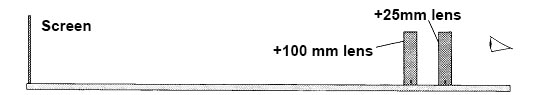
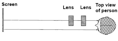
Use the +25 mm lens as the eye lens and the +100 mm lens as the objective. Place the lenses near one end of the optical bench and the screen at the other end, as shown below. Tape a piece of graph paper to the screen. (Graph paper and tape are in the lab room.)
-
Look through the eye lens, and focus the image of the graph paper by moving the objective.
-
(This procedure is a bit complex. Try your best and do not waste a lot of time on it.) Eliminate parallax by moving the eye lens until the image is in the same plane as the object (the screen). To observe the parallax, open both eyes and look through the lens at the image with one eye, while looking around the edge of the lens directly at the object with the other eye. Refer to the figures below. The lines of the image (solid lines in the figure below) will be superimposed on the lines of the object (dotted lines in the figure below). Move your head back and forth, and up and down. As you move your head, the lines of the image will move relative to the lines of the object due to parallax. To eliminate parallax, adjust the eye lens until the image lines do not move relative to the object lines when you move your head. When there is no parallax, the lines in the center of the lens appear to be stuck to the object lines. (Even when there is no parallax, the lines may appear to move near the edge of the lens because of lens aberrations.)
-
Measure the magnification of this telescope by counting the number of squares in the object that lie along a side of one square of the image. To do this, you must view the image through the telescope with one eye, while looking directly at the object with the other eye. Record the observed magnification in step 5.
-
The theoretical magnification for objects at infinity is equal to the ratio of the focal lengths. Record and compare the theoretical and observed magnifications below.
Observed magnification =
Theoretical magnification =
ADDITIONAL CREDIT PART 1: MEASURING A GLASSES PRESCRIPTION (3 mills)
The inverse of the focal length of a lens, \(P = 1/f\), is called the power of the lens. The units of power are inverse meters which are renamed diopters, a unit commonly used by optometrists and opticians. The larger the power, the more strongly the lens converges rays. You can show that when two thin lenses are placed close together (so that the distance between them is much less than the focal lengths), the power \(P_{\textrm{T}}\) of the combined lenses is the sum of the powers \(P_1\) and \(P_2\) of the individual lenses:
\begin{eqnarray} P_{\textrm{T}} &=& P_1 + P_2 \end{eqnarray}
or
\begin{eqnarray} 1/f_{\textrm{T}} &=& 1/f_1 + 1/f_2. \end{eqnarray}
The closest distance at which you can focus your eyes clearly (when you are exerting maximum muscle tension on your eye lens) is called your near point. The farthest distance at which you can focus your eyes clearly (when your focusing muscles are relaxed) is called your far point. Ideally, your far point is at infinity, and your near point is at least as small as 25 cm so you can read easily. If you are nearsighted, then your far point is at some finite distance; you cannot focus distant objects clearly. If you are farsighted, then your far point is “beyond infinity”, so to speak, so that you need to exert eye-lens muscle tension even to focus distant objects. As you grow older, your power of accommodation (i.e., your ability to change the focal length of your eye lens) weakens and your near point moves out, so that you must have corrective lenses to focus on close objects, such as for reading. Thus, you notice older persons wearing reading glasses.
You may be wearing glasses, contact lenses, or have had laser eye surgery to correct your vision — or you may be lucky and have “perfect” vision without correction. In any case, use a meter stick (or other ruler) and the card with fine print to measure your near point (with correction, if any) as in the illustration below. The purpose of laying the meter stick on the table is to avoid poking it toward your eye.
Move the card in to the closest distance that you can focus clearly.
Near-point distance (corrected) =
If you are nearsighted and wearing glasses, take off your glasses and measure your far point. (If you are wearing contacts, you may remove a contact and try this, but the step is optional.)
Far-point distance (uncorrected) =
If you or your lab partner are nearsighted and wearing glasses, determine your glasses prescription as instructed below. If neither you nor your partner is nearsighted and wearing glasses, use the (uncorrected) data for Dr. Art Huffman: far point = 20 cm, near point = 18 cm. (Yes, his vision is that bad!)
If the eye is nearsighted, we want to put a diverging lens in front of it, which will shift the uncorrected far point to infinity. We can use the formula above to find the focal length of the glasses-eye combination. Let the (uncorrected) far-point distance be \(d\), the eye-to-retina distance be \(i\), the focal length of the eye lens while relaxed be \(f_{\textrm{f}}\), and the focal length of the glasses be \(f_{\textrm{g}}\):
\begin{eqnarray} \textrm{Without glasses:} &\hspace{10pt}& 1/d + 1/i = 1/f_{\textrm{f}} \\ \textrm{With glasses:} &\hspace{10pt}& 1/\infty + 1/i = 1/f_{\textrm{f}} + 1/f_{\textrm{g}}. \end{eqnarray}
Subtracting the first equation from the second gives the power \(P_{\textrm{g}}\) of the glasses:
\begin{eqnarray} P_{\textrm{g}} &=& 1/f_{\textrm{g}} = -1/d. \end{eqnarray}
Compute your glasses prescription (or Art's) in diopters:
ADDITIONAL CREDIT PART 2: MEASURING THE FOCAL LENGTH OF A DIVERGING LENS (2 mills)
Devise a way, using your optical bench, to measure the focal length of a diverging lens. Then measure the focal length of your glasses as in Additional Credit Part 1, or measure the focal length of one of the unknown lenses supplied in the lab.
Sketch your plan for measuring the focal length of a diverging lens below, and report the measured power of the glasses or of the unknown lens.
Attachments: