
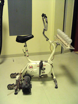
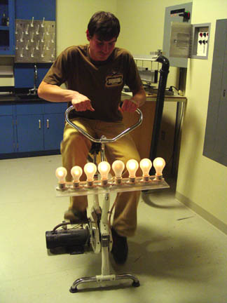
A person pushes the pedals of the the bicycle to generate enough current to light up to eight parallel light bulbs. The more bulbs the more resistance. Try it. you'll see.
Two solenoid coils connected by wires are arranged so that magnets on springs oscillate in them. When one magnet is set oscillating, the induced current causes the other to oscillate also.
In a variation of this demonstration known as Nefkens's Telephone the two coils are set on opposite sides of the lecture hall with a long wire connecting them. Just by arranging some pieces of iron and copper in the right way, movement here causes movement over there -- an astonishing achievement of the mind of Man.
Short the leads of one of the coils and the oscillation of the magnets will be rapidly damped out by Lenz's Law.
This apparatus is used in an 8E lab experiment. A spherical electron tube is mounted inside of a Helmholtz coil setup. The electrons are projected to circle in the magnetic field, and you measure the radius of the circle, the current to the Helmholtz coils, and the accelerating voltage to determine e/m. The electron path is made visible by dim ionization of the residual gas in the tube.
If the tube is twisted a little inside the coils, the circle becomes a helix. This is a very pretty demonstration of the path of charged particles in a magnetic field.
- The following experiments may fatally damage your microwave and will probably start a fire in your kitchen.
- A microwave oven can be used for various demonstrations including standing waves in an overmoded wave guide cavity, heating by electromagnetic waves, creation of plasma balls fed by microwaves, conduction of hot glass, superheating of fluids and others. A neon tube array shows the electric field pattern. Click on the picture of the array below to see a video of the array in the oven.
E-field in Microwave Oven
Lightbulbs in a Microwave Oven
Microwave Plasma Balls
A magnet thrust into a coil produces a noticable deviation on a table galvanometer. Or the coil can be moved over the magnet. (See also Special Relativity Demonstration [1])
In another demonstration two large coils are placed adjacent to each other, one connected to the galvanometer. When the other is pulsed with a battery, the induced current will be noted on the meter. You can emphasize the point that a steady current in the primary will induce no current in the secondary. If an iron core is positioned through the two coils, the galvanometer readings will become dramatically larger.
Faraday Bulb
A coil connected to a small bulb is mounted on a disk. When the disk spins the coil through the poles of a magnet, the bulb lights for that part of the arc for which the coil is passing through the magnet.
A small vacuum tube transmitter feeds an electric dipole antenna. The EM waves with l = 3m are picked up by a handheld dipole receiving antenna and detected by a peanut light bulb. Several aspects of dipole radiation can be illustrated with this setup:
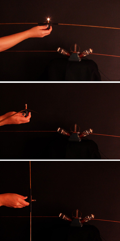
Modern Version of Hertz Wave Experiment
A VCR is set up with a videotape broadcasting on Ch 3. Instead of wiring the cable directly to the TV, it goes instead to a folded dipole antenna optimized for the frequency of Ch 3, which is 60 66 MHz. The receiver is a second folded dipole antenna which is connected to the TV (tuned to Ch 3), which acts as the detector.
It is easy to diplay the polarization of the EM waves by turning one of the dipole antennas at a right angle to the other. If there are standing waves in the room these can be seen by moving one antenna in relation to the other. From the distance between nodes the wavelength can be determined.
TV stations have a 6 MHz bandwidth. Channel 3 is 60 66 MHz which gives a wavelength of 5 meters. How are TV antenna oriented on a roof? That gives the polarization.
FM frequencies are 88 108 MHz
Broadcast antenna are horizontal or 45o
AM 550 1600 kHz
Vertically polarized antenna, usually center-fed dipole with image in ground.
Cellular phone antenna usually have a 10-60cm wavelength. From the antenna size you can guess the frequency.
The antenna used in this demo are folded dipole type made from 300 Ohm twin lead. They are connected to 75 Ohm cable through impedance transformers.
To see how the radio spectrum is divided up by users press here. [2]
A radio transmitting apparatus used by Marconi in 1895 in some of his earliest experiments.
You can show the rainbow spectrum of visible light with a dispersing prism [4] in front of a slide projector. A transparency of Maxwell's Rainbow, next page, is available.
An infrared detector connected to a meter visible to the class is placed beyond the red in the spectrum above. Why is the signal so small? Doesn't the tungsten lamp peak in the infrared? Ah, remove the "heat" absorbing glass element from the projector and the signal becomes large.
Ultraviolet light and the fact that it is absorbed by window glass can be demonstrated in connection with the photoelectric effect [5].
A radiometer consists of a spinner in a near vacuum with vanes silvered on one side and blackened on the other. When light, particularly infrared, falls on the radiometer, the black sides of the vanes become hotter and drive residual air molecules away from them, propelling the vanes around. (The rotation direction is contrary to that produced by radiation pressure, a smaller force.) A flashlight will operate the radiometer, but a match flame, which has more infrared, does much better. (Low powered lasers, of course, have too little energy to operate the radiometer.) Parabolic reflectors can be used to focus the infrared from a match or electric coil to spin the radiometer across the lecture hall.
Jumping Ring
A light aluminum ring, when placed on the iron core sticking out of a large AC electromagnet, is ejected violently into the air when the electro-magnet is activated. The conceptual explanation is that the AC magnet is continually reversing polarity, and induces a voltage in the ring so the ring's magnetic field continually opposes (repels) that of the iron core.
Copper rings and split rings are available to test also. A heavier copper ring will float midway up the iron core. When the ring is forced down on the iron core, it becomes very hot. A split ring will not move; it is not a complete circuit.
Magnetically Damped Pendulum
A pendulum with various disk is arranged to swing through the poles of a powerful permanent magnet. A solid aluminum disk is stopped on the first pass. An aluminum disk slotted to reduce eddy currents is moderately damped, and a cardboard disk swings freely.
Various rectangular plates can be released to fall through the poles of the magnet. An aluminum plate slides viscously, a slotted plate more rapidly, and a cardboard plate is unaffected.
Russian Version
Two rings are balanced on an arm which swings freely on a bearing. When a magnet is thrust into one ring, it is repelled away. (You can use this to illustrate the answer to the question in connection with the Faraday demonstration [6], "Where does the energy come from that moves the galvanometer needle?"). When the magnet is pulled out, the ring is attracted towards it. The other ring is split; thrusting a magnet in and out has no effect on it.
Osheroff Demonstration
A copper plate is cooled with liquid nitrogen to improve its conductivity. A falling magnet bounces without hitting the plate and lands on it's edge.
A large DC motor, with easily visible coils and split-ring commutator, operates from a 6 V battery. The motor can be rewired so that the field coils are energized. If the armature is now rotated by hand, a DC current is generated.
An AC-DC motor-generator has a single turn armature and both split and slip rings to act as a DC motor or an AC or DC motor or generator.
A hand-crank generator illuminates a neon bulb when cranked vigorously.
A small coil, mounted near the edge of a plexiglass disc, is connected to a peanut bulb. When the disc is spun between the poles of a powerful permanent magnet, the bulb is seen to be lit for that part of the circumference for which the coil passes through the poles of the electromagnet.
A tin can induction motor is demonstrated by holding a tin can on a special handle near two large coils at right angles. The coils are connected to the AC line, but one has a series capacitor to shift its phase 90° with respect to the other. This illustrates the starting circuit of the most common type of electric motor, the induction motor.
The hand-cranked generator is wired through a knife switch to an incandescent bulb. You can use a student volunteer to verify that it is much harder to crank the generator when the bulb is in the circuit, than when no current is being drawn. Ask your class why.
The Magnetic Levitator [7] has two coils at right angles connected to 120 VAC so the coils are 90° out of phase. These will rotate the suspended ball as in the tin can motor.
The secondary of a 1:1 transformer is hooked through a switch to a light bulb. The primary is hooked in series with another light bulb to the 120 V. line. When the switch is open neither bulb lights; the inductive reactance of the primary keeps the current small in the primary circuit. But when the switch is closed, both bulbs light! Now the secondary circuit is drawing current, so the mutual inductance of the two coils reduces the effective inductive reactance of the primary and enough current flows in the primary circuit to light its bulb.
Alternatively, conservation of energy tells us that the primary current must increase so that energy can be delivered to the secondary bulb through the magnetic fields linking the coils.
![]()
The Paul Trap, or rotating saddle trap, is an analogy to RF-electric quadrupole ion traping.
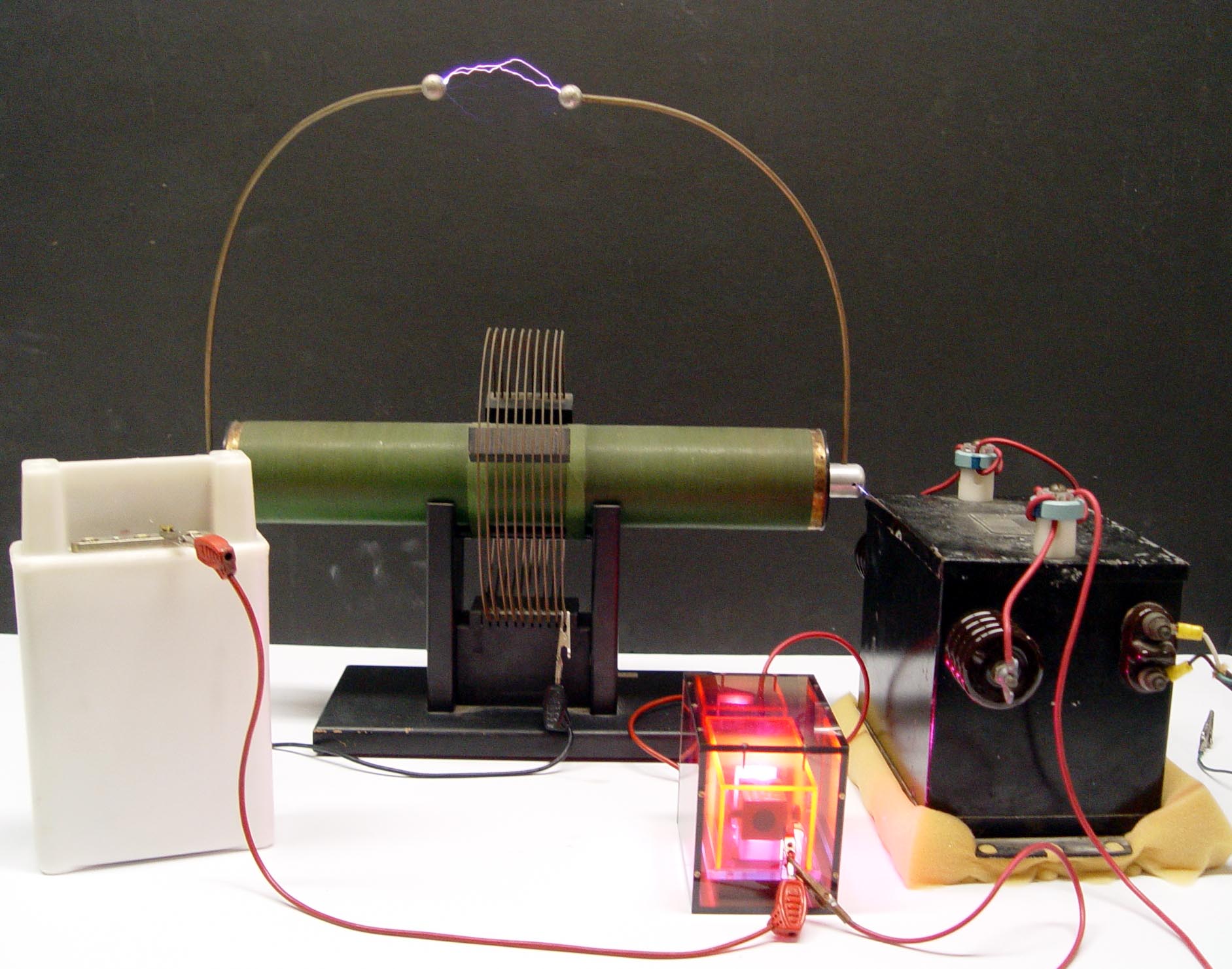
A Tesla coil is a high frequency, very high voltage transformer. The operation and circuit are described below. Our smaller Tesla coil radiates enough RF to illuminate a fluorescent tube a foot away. You can draw a one foot arc into your body, using a metal rod; the frequency is so high that the ions in your body do not have time to move far enough to do damage.
The Giant Tesla Coil generates a four foot discharge that will illuminate fluorescent tubes many feet away, and will generally terrify anyone anywhere near it. People with pace makers are supposed to move to the back of the room.
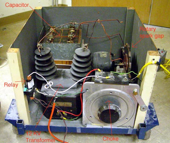
Tesla Circuit Operation
A preliminary step-up transformer boosts the line voltage to ten or twenty thousand volts. (A neon sign transformer is used for this purpose in the giant Tesla coil.) This voltage arcs across the spark gap F at 60 Hz, ringing the tuned circuit consisting of the capacitor C and the Tesla primary (a few turns) at 1-3 MHz. The Tesla secondary (many fine turns) has its own resonant frequency determined by its inductance and the internally distributed capacitance between its windings. The primary LC circuit is tuned to this resonant frequency for maximum coupling.
A spectacular demonstration with the small Tesla coil is to hold a fluorescent bulb in one hand and a metal rod in the other. When you draw an arc with the metal rod from the Tesla coil, the current passes through your body and lights the bulb. The voltage is over 1 million volts; why doesn't it shock or kill you? There are a number of hypotheses on this: a. The skin effect -- the current travels in the outer dead layer of skin. b. Human nerve circuits do not respond to high frequencies like 1 MHz, perhaps because of the reason mentioned above; there isn't time for the sodium and potassium ions to move far in the nerve cells. c. The impedance of the Tesla coil is very high, and it therefore induces only very small currents in humans.
A skin depth calculation using the conductivity of sea water, sigma = 4 mhos/m, gives a depth of 0.25cm, so this effect would not play a large role in protecting you, at least from pain stimulation on the skin surface. The answer is probably a combination of effects b and c from above. The current through the body is too small to generate enough heat to injure the person, and the high frequency does not stimulate pain nerves, or induce muscle contraction.
Our giant Tesla coil does sting you if you get into its circuit path to the ground. Tesla coil builders claim that the "gentleness" of the particular Tesla coil depends on the cleanness of the separation of 60 Hz and the high frequency at the spark gap.
A nice description of how the tesla coil circuit really works is here [8].
A demonstration transformer steps the 110 V AC line voltage up to 10,000 V for a Jacob's Ladder. The current arcs across the shortest distance between two upright conductors. Once started the arc rises, owing to the heated air, and jumps over a distance of several inches.
A secondary of few turns can be substituted to make a stepdown transformer. The low voltage - high current can be used to spot weld sheet metal or to melt a tin ring.
Transmission Line
![]()
A signal generator capable of 10 MHz is hooked to a T-connector at channel 2 of an oscilloscope through an 8 meter 50 ohm cable as shown above. Channel 1 of the scope is hooked to the same source through a short cable.
Input a pulse at 1 MHz; sweep at 0.5 ms/cm
Input a sine wave
Suggested by Brad Tippens
In the ideal case the magnetic field lines of a toroidal coil are entirely contained witnin tne coil and = 0 outside. This can be checked by using a flip-coil, Hall probe, or compass needle near the toroidal coil.
However, the lines of vector potential circle the flux lines:
So A is not zero outside the coil.
If a wire is threaded through the hole of the toroid and returned through the hole, case 1, no galvanometer deflection is seen as B is switched on and off. But if the wire is threaded through the hole and returned around the coil, case 2, a galvanometer deflection will be seen from = -d/dt.
Links:
[1] https://demoweb.physics.ucla.edu/node/199
[2] http://www.ntia.doc.gov/osmhome/allochrt.pdf
[3] https://demoweb.physics.ucla.edu/sites/default/files/HertzWavesm.jpg
[4] https://demoweb.physics.ucla.edu/node/208
[5] https://demoweb.physics.ucla.edu/node/209
[6] https://demoweb.physics.ucla.edu/node/197
[7] https://demoweb.physics.ucla.edu/node/205
[8] http://www.richieburnett.co.uk/operation.html