A Set of First Day Demos with Audience Appeal and Discussion
Some instructors like to give a "magic show" on the first day of class to illustrate some of the physics that will be covered during the quarter. Examples of mechanics demos with audience appeal are (see entry further in catalog for illustration and more description):
Unidentified Rolling Objects [1]
Turntable and Bicycle Wheel [5]
Another suggestion for the first day of class is to do a set of demos that review a little high school physics and lead into the subjects to be covered in the first two weeks. Here is a sample scenario:
Start with Drop Two Balls [6]. Ask your students, "If I drop this steel ball and this wooden ball simultaneously from the same height, which will hit the ground first?" You will be surprised at the various answers, even from a Physics 8A class. Solicit explanations from several different students of their reasoning; this will give you an idea of the level of the class. If most of the students claim the balls will hit the ground at the same time ask, "What if I drop this ball and this sheet of paper?" This can then lead into a discussion of the effects of air resistance and what factors influence it, like the area fronting the wind. Lester Hirsch suggests: Borrow the two sheets of paper from two different students. Tell them not to tear the pages out of their notebooks; you are going to return the pages. Crumple one up into a ball and drop it simultaneously with a flat sheet. Here we have isolated the effect of air resistance by dropping two objects with the same mass, but different shapes. After the demonstration hand the flat sheet back to the first student, and carefully smooth out the crumpled sheet and hand it back to the second student. When he makes a face, tell the class that conservation has to start somewhere, and that he has to be the one this time!
To make this demonstration somewhat more quantitative, you may wish project a slide of a wooden ball, a steel ball, and a ping-pong ball falling, photographed at 1/20 sec. intervals. (See Three Balls Falling [7])
The Guinea and Feather Tube [8] might well be used in this discussion also.
If you establish in a high level class that all of the students are pretty clear on the concepts of equal gravitational acceleration for different masses and effect of air resistance, try the following, "According to Newton's Third Law, what force is equal and opposite the weight of this steel ball I am holding in my hand?" You will get a variety of different answers to this question. After the discussion establishes that the third law pair to the weight of the ball acts on the entire planet Earth, ask, "So, according to Newton's Third Law, the steel ball exerts a force equal to its weight on planet Earth. As the two balls fall, doesn't the steel ball pull the Earth over towards it more than the wooden ball, so the steel ball must really strike the Earth first, even if we neglect air resistance?"
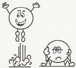
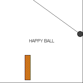
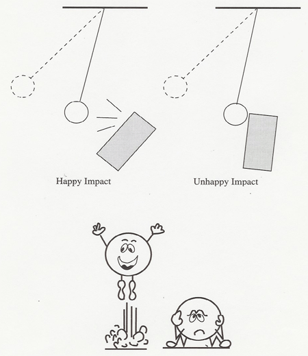
As a final first-day demonstration, drop the "happy" and "unhappy" balls to show that objects that look identical may have very different physical properties.
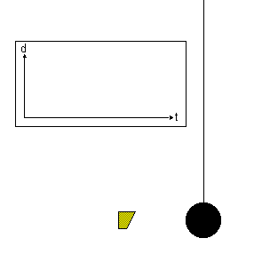
This very simple demonstration of a pendulum swinging above two magnets illustrates that Newton's laws do not always lead to predictable orderly motion. The pendulum bob is released from various initial positions, and it eventually comes to rest over one of the magnets, usually after undergoing complex irregular motion, often jumping from one magnet to the other. If you could accurately mark the release points for which the bob winds up over magnet one, you would find a "fractal" curve which is complex under any magnification. Points infinitesimally close to a point for which the bob winds up over magnet one will lead to the bob finishing over magnet two. It is not really practical to develop this curve in class, but the chaotic irregular motion of the bob is striking. This demo is suggested in Turning the World Inside Out by Robert Ehrlich (Princeton University Press 1990).
There is also a compound pendulum which shows chaotic motion (see Compound Chaotic Pendulum [9]).
a. Unpredictable discs
Ask the class which of two identical looking discs will roll down an inclined plane the fastest. Most students will say they will roll equally, but one rolls down, and the other rolls up the inclined plane!
Also two identical looking cylinders roll down at different rates.
b. Premature stopping of cylinder
A cylinder rolls half-way down an inclined plane and then stops.
c. Reversing cylinder
A cylinder rolls down the inclined plane, and then rolls back up!
d. Unpredictable Pendulum
Pendulum swings irregularly around, deflected by a hidden magnet.
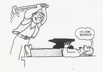
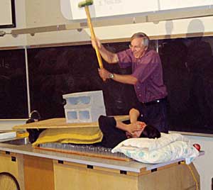
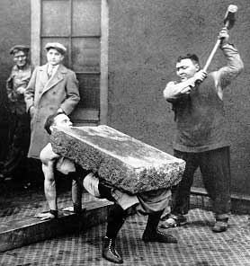
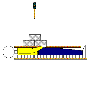
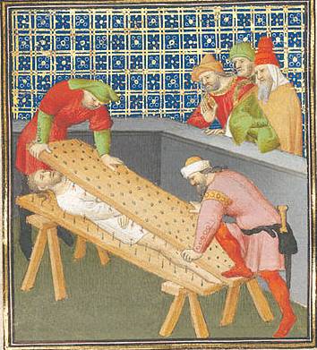
A "volunteer" removes glasses and jewelry and lies on a bed of 4000 nails. A male volunteer can take off his shirt so that his bare skin is against the nails. A plywood sheet is placed over him and several concrete blocks piled on top. The demonstrator then smashes the blocks with a sledge hammer.
Several physics principles are involved here. The force from any one nail is reduced by spreading the weight over many nails. The inertia of the blocks partially protects the person below from the force of impact. The smashing of the blocks absorbs much of the energy of the blow.

Using too few nails in this demo was a form of torture. In the illustration below Roman consul Marcus Atilius Regulus is tortured to death by Carthaginians in about 255 BC. The illustration was painted in about 1415 in Paris.
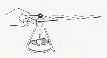
A card with a small ball is placed over a flask. When the card is flicked away with the finger, the ball will not move with it but will fall straight down into the flask.
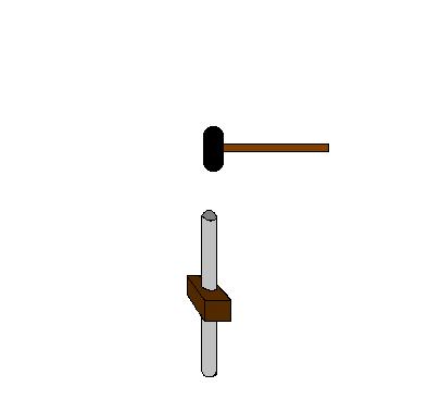
A PVC tube goes through the center of a wooden block, which is free to move along the tube after overcoming some amount of friction. As you hammer down on the tube while holding on to it with one hand the block moves up along the tube.
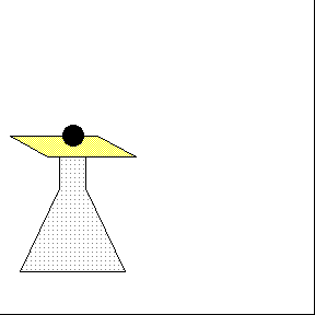
This is a dramatic demonstration of inertia. A metal hoop of spring steel is balanced on the mouth of a flask, and a piece of chalk is balanced on the hoop, directly over the mouth of the flask. The object is to snatch the hoop away so the chalk falls into the flask. Tell your audience that this is a difficult demonstration and you need a couple of practice shots first. In your "practice shots" grab the hoop by its leading edge so the top is compressed upward ejecting the chalk wildly into the air. After telling the audience you are now ready to try it for real, grab the hoop by its trailing edge so its top is pulled out from under the chalk, dropping the chalk neatly into the flask! (From The Physics Teacher, Feb. 1982).
A massive ball is suspended by a string with a string below. Using a rod, the demonstrator pulls or jerks down on the lower string. A steady pull always breaks the upper string; a jerk always breaks the lower string.
 With a Jerk |
 Pulling Steadily |
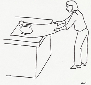
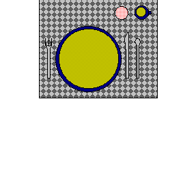
Bring down the house with this old favorite. A plate and silverware are laid out in a place setting on a sheet of paper. A glass of water, beer, or wine adds impact. With a swift jerk the demonstrator pulls out the paper, leaving the place setting intact.
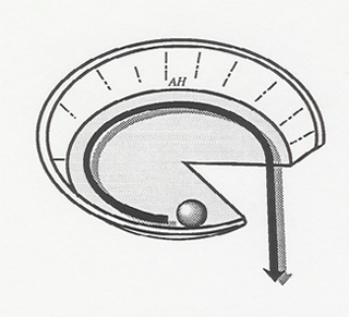
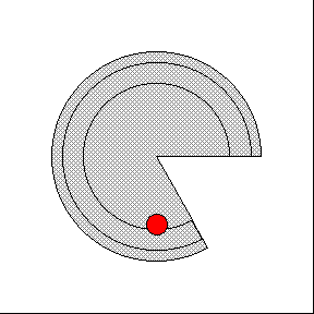
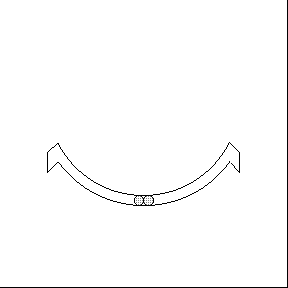
Which way will the Moon go if the earth's gravity were suddenly switched off? The Pie Plate demo gives a good analogy. Spin a ball around the inside rim of the plate. The inward force of the rim keeps the ball in circular motion. But when the rim ends, the ball flies off in a straight line, obeying Newton’s First Law.
|
| A Scientific American article ("Intuitive Physics" by Michael McCloskey, Scientific American, April 1983) discusses how students, when asked which way the ball will go upon leaving the pie plate before having taken a course in physics, will usually answer that the ball will continue to curve around. Of course, right after taking physics the students (at least the ones that pass the course!) know that the ball moves off in a straight line. But a few years after the course, the ball starts to curve again! The students were enlightened; they knew the truth, but then they fell back into darkness! (The same article discusses several other misconceptions of motion you may wish to discuss with your students.) |
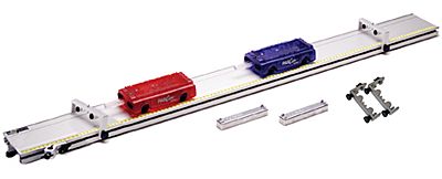
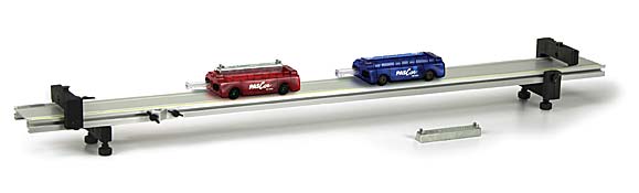
In addition to its usefulness in qualitative demonstrations of linear motion and collisions the dynamics track shown below can be used in conjunction with Data Studio and a motion sensor to measure and plot the position, velocity and acceleration of a Pasco cart as a function of time.

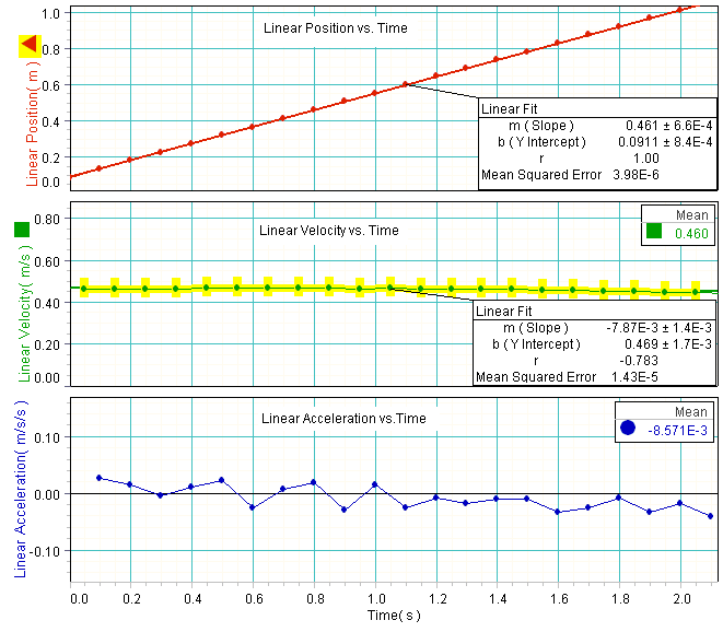
In the following Data Studio experiment for constant linear motion, the Pasco track was propped up slightly on one end with adequate metal slugs to compensate for friction. Then the cart was given a slight push to achieve constant velocity. The motion sensor was used to measure and graph the cart's position as a function of time. The graph shows that the position changes linearly as a function of time. A linear fit to the position vs. time curve gives the slope to be 0.45 m/s. This constant value corresponds to the average and instantaneous velocities for this experiment. Furthermore, it is within experimental error of the mean of the velocity vs. time curve (0.46 m/s). Taking the slope of the velocity vs. time curve, we find that it is zero and therefore have zero acceleration -- also demonstrated experimentally.
Various other linear motion demonstrations can be performed with the dynamics track which also allow for quantitative analysis. The track may be set up with two electronic timers that measure the time it takes a 10 cm flag mounted on a cart to pass in front of an infrared sensor. Thus, these timers are measuring (the reciprocal of) the velocity of the carts.
Another timer is available to measure the elapsed time for a cart to cover a given distance.
a. Newton's 1st law A cart is set moving along the track past the two velocity times. The track can be set up to compensate for friction such that the velocity of the glider remains essentially constant.

b. Gravitational Acceleration If one end of the track is raised slightly, measurements can be taken of a cart accelerating down the track.

c. Newton's 2nd Law A ribbon is attached to a cart and passed over a frictionless pulley to a falling weight. By varying the mass of the weight and the cart, measurements can be taken verifying Newton's 2nd Law.
d. Collisions and Explosions Elastic and ineleastic collisions between carts can be demonstrated as one end of the carts are equipped with magnets and the other end with Velcro. A moving cart collides elastically with a stationary cart of equal mass using the magnetic ends. The originally stationary cart moves away with all the velocity. Completely inelastic collisions result by colliding the Velcro ends of the carts. A carts velocity is measured before and after it has collided inelastically with another cart of equal mass. It is demonstrated that the velocity of the two carts after the collision is half the initial value.
|
Elastic Collision |
Inelastic Collision |
|---|---|
 |
 |
Explosions are demonstrated by touching the ends of two carts together and releasing an internal plunger from one of the carts.
|
Explosion |
|---|
 |
All of the above demos may also be demonstrated with the air track at the instructor's request. The air track has an advantage over the dynamics track in that there is less friction associated with it. However, the air track has a draw-back in that it is much noisier than the dynamics track and in a lecture setting it is difficult for the instructor to be heard.
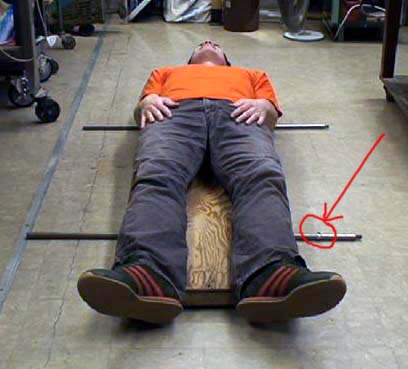
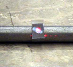
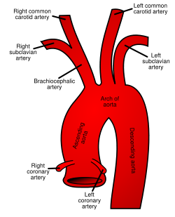
A person lies down on a flat board set on rollers. A laser beam is directed at a tiny mirror positioned on one of the rollers. The laser beam is projected onto the ceiling or wall. The beating of the person's heart causes a slight movement in the body as indicated by the laser. This upward movement of the body is due to the 3rd Law reaction force of the blood being pumped to the lower body. The left ventricle of the heart squeezes blood upward into the aorta shown below. At the peak of the contraction, about 80 grams of blood is moving upward at 30 cm/s. The aorta does a U-turn forcing most of the blood to flow down to the lower body. The aorta and body force the blood down and in turn the body is forced up. The amount is too small to be seen by eye but can be seen when "amplified" by the laser-mirror arrangement used in the demonstration. It can also be seen when standing quietly on a weight scale if the scale is sensitive enough and the vibration is not damped by the scale mechanism. Your weight decreases slightly when the blood slams into the top of the aorta.
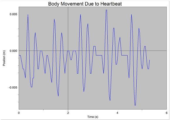
A video of the movement of the body as detected by the laser-mirror setup as well as a graph tracing the motion are provided below.
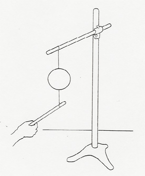
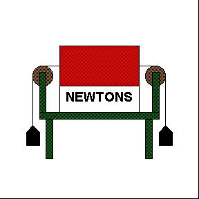
A 1 kg mass weighs 9.8 N as checked by a spring scale. Two 1 kg masses are hooked on the ends of a string which is passed over a pair of pulleys, and the spring scale is placed in the center of the string to measure the tension as shown. The scale is covered with a cloth to hide its reading, and the class is then asked to predict whether the scale will read 0, 9.8, or 19.6 N.
Water Rocket — A toy rocket is loaded with water and compressed air and shot across the room. It can also be fired with air only (no water in it) to show the difference.
C02 rocket — A rod mounted on the end of a shaft is free to turn about the shaft's axis. At the end of the rod is a C02 cartridge. When the cartridge is punctured, the escaping gasses propel the rod with considerable speed.
Hero's engine — spins by the reaction force of escaping steam.
The dynamics track cart has a sail and a battery operated propeller; both are removable. If the propeller is removed and held so it blows against the sail, the cart will roll to the left. If the sail is removed and the propeller mounted alone, the cart will accelerate to the right. If both the sail and the propeller are mounted, the instructor can ask the students which way the cart will roll.
From S.R. Smith and J.D. Wilson, Phys. Teacher, Apr. 72, pp 208.

Note: The above demos may also be demonstrated with the air track at the instructor's request. The air track has an advantage over the dynamics track in that there is less friction associated with it. However, the air track has a draw-back in that it is much nosier than the dynamics track and in a lecture setting it is difficult for the instructor to be heard.
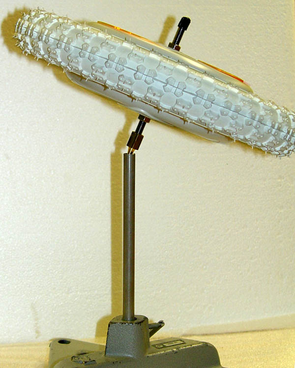
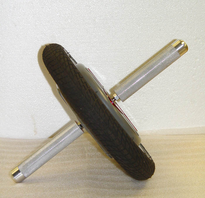
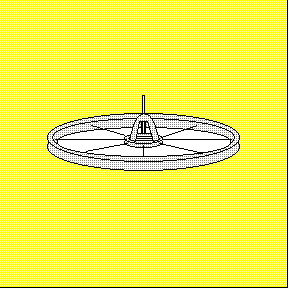
A spinning bicycle wheel suspended by a rope from one end of its axle makes an impressive gyro. A skillful demonstrator can start the wheel precessing smoothly so that the axle remains horizontal.
Other gyros available:
Two standard gyros spun up with a small motor.

Fully gimboled gyro to demonstrate maintenance of axis of rotation and inertial guidence.

Gyrowheel a small bicycle wheel with a motorized gyro inside, can be used on the rotating platform or as a precessing top
Cenco top a large bicycle wheel sized gyro, the center of mass of which can be varied above and below the point of support.
Massive air bearing ball gyro operates with so little friction that the rate of rotation can be made smaller than the rate of precession. Measurements can be taken to check the relationship between the angular velocities of rotation and precession.
Various tops are available including a "tippy top" consisting of a hemisphere with an axle shaft above. When set spinning on the hemisphere, the top will flip upside down and spin on its axle.
A "perpetual motion" top spins indefinitely with no apparent external energy source.
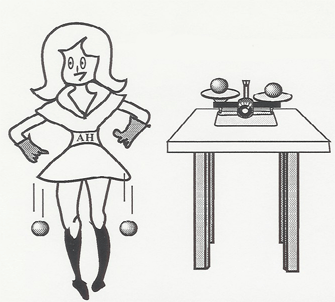
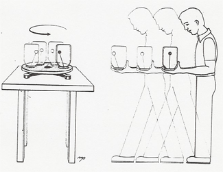
a. Have a volunteer stand on the turntable holding the bicycle wheel vertically. Start the wheel spinning and have the volunteer tilt it up or down towards a horizontal position. The demonstrator can steer himself around to any position with proper tilts of the wheel.
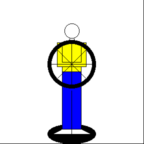
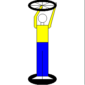
b. Stand on the turntable holding the bicycle wheel horizontally, and start it spinning yourself. You will start spinning the opposite direction to conserve angular momentum.
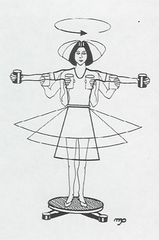
For the ice skater effect, have a student stand on the turntable with arms outstretched holding one or two kilogram weights. Start her spinning slowly, and then have her pull her arms into her chest. You must start her spinning quite slowly, or when she pulls her arms in, she will be thrown off the turntable.

A spring gun, clamped to the lecture table, fires a steel ball into a pendulum bob, which traps it. The pendulum bob swings away and is held at the highest position reached by a ratchet. The laws of conservation of energy and momentum for the inelastic collision of the steel ball with the pendulum bob are used to calculate the velocity of the ball as fired by the gun from the data of the height of rise of the bob and the mass of the ball and the bob.
The pendulum bob is then moved out of the way so the gun can fire across the lecture hall. Tne laws of ballistics are used to calculate the spot on the floor the ball will hit, and a metal can is placed on the predicted spot to catch the ball.

A toy LGB train has a flat car with a vertically mounted gun, actuated by a flashlight. When the train is at rest, the projectile ball is shot vertically upward and falls back down into the gun muzzle. If the train is moving along a straight section of track, the ball is still caught by the gun, even though the trajectory of the ball is now a parabola. The train can even be sent through a tunnel so the ball is fired up before the flat car enters the tunnel, passes over the tunnel, and is caught as the flat car exists the tunnel.
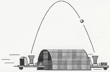
If the gun is fired as the train is rounding a curved section of track, the ball will not be caught, illustrating the restriction of special relativity to inertial frames.
This is a fairly elaborate demonstration, and several people are required to set it up, the set-up time often running five minutes or so into the beginning of class. Please give extra notice for your planned use.
![]()
Instructions
Do not run above 18 V. Train will wreck!
(There is probably a 2 V margin up to 20 V, but a wreck causes serious damage.)
The switch on the battery car turns on the system. Switch off after use to conserve batteries. (The switch on the gun car should be left on.)
llustrates that the vertically downward acceleration is independent of the horizontal velocity. See: Horizontal and Vertical Ball Drop (Gravitational Acceleration) [10].

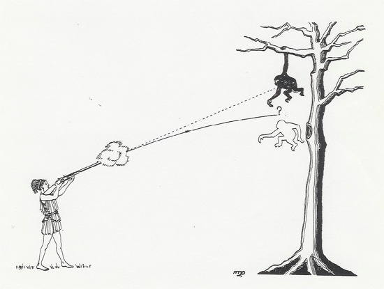
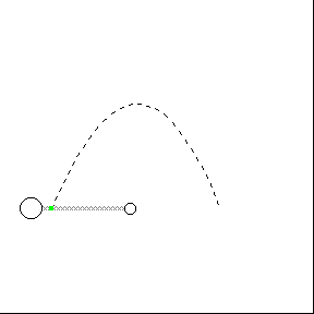
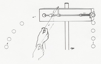
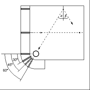
A monkey hanging from the branch of a tree in Africa is spotted by a small game hunter. But this is no ordinary monkey; this monkey knows some physics. He sees that the barrel of the gun is pointed directly at him and reasons that if he lets go of the branch at the right instant, the bullet will pass over his head. But he knows that the sound from the gun will not reach him much before the bullet, and maybe even after, so he decides to watch for the light flash from the gun, knowing that the light reaches him almost instantly, and to let go the instant he sees the flash. Is his reasoning correct?
Modern technology gives us a 25mm, laser guided, anti simian cannon. The monkey and hunter demonstration is on a wheeled table with the elevation of the gun controlled by a crank. The gun is fired by compressed air from a pressure cooker tank. A laser beams through the gun barrel so all can see where the straight line of the gun-aim is directed.
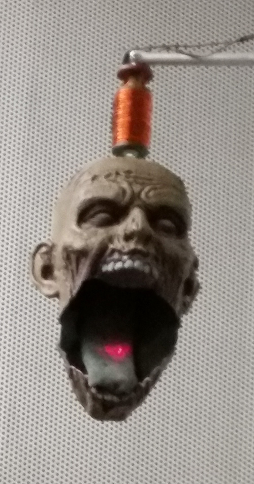
Besides a monkey target, we also have a zombie target, so if monkey hunter is not politically correct, you can call this, shoot the zombie instead. You can see a video test firing with the zombie here [11]. A picture of the zombie with the laser spot is shown below.
The illustration below is available on a viewgraph for overhead projection to the class.
Zombie head with laser spot.
Mouse over the animation below to see how the monkey hunter works at two different pressures.![]()
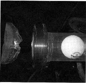
A ping-pong ball is placed inside the PVC tube and both ends are sealed with pieces of Mylar after which the tube is evacuated to ~ 10 Torr. When the Mylar piece near the ball end is punctured, the ball accelerates due to the expanding air behind it, leaving the tube at speed close to 300 m/s.
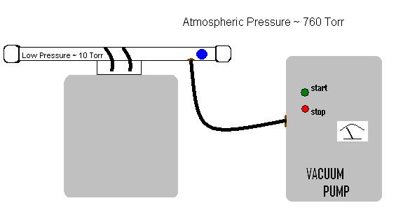
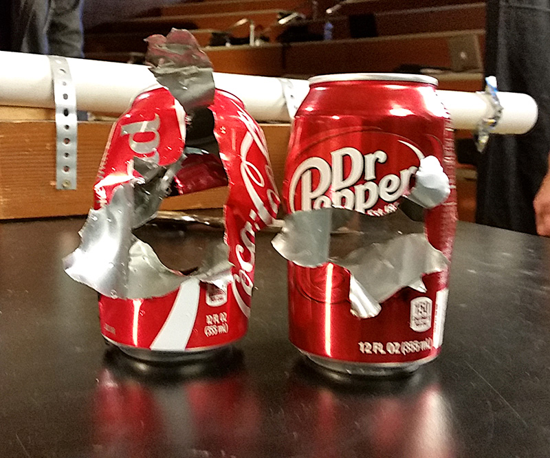
The ping pong ball can tear through two aluminum cans.
It is interesting to note that the Mylar piece used as a barrier at the exit end becomes detached before the ball reaches it. The following photograph is taken from G. Olson, R. Peterson, B. Pulford, M. Seaberg, K. Stein, R. Weber, The Role of Shock Waves in Expansion Tube Accelerators, Am. J. Phys, 74 (12), December 2006, p. 1071-1076.
The explanation requires consideration of nonlinear gas dynamics and shock behavior. Compression waves traveling ahead of the ball quickly develop into a shock wave that reflects off the exit end of the tube and in turn off the ball several times. With each reflection there is a localized pressure and temperature increase so that by the third or fourth one a heated pressure pulse builds up at the exit end and is enough to remove the barrier piece.
A spring gun is arranged to fire at various angles to illustrate that the maximum range of a gun occurs at 45°, the gun has equal ranges of the angles 45° �, etc.
Ballistic Motion is studied with a water stream that continually shows the parabolic trajectory of particles in a gravitational field. Measuring rulers hang down near the stream so that you can show, for example, that the stream falls a distance 1/2 gt� below the straight line it would have followed had there been no gravity. You can vary the angle of projection to show the 45° angle of greatest range, equal ranges at equal angles about 45°, etc. This demostration has audience appeal as the water pressure varies, and the instructor struggles to make the measurements while occasionally getting spritzed.
a. An irregularly sharped wooden block is suspended from various points, and a plumb line is dropped to determine the center of gravity.
b. A double cone will roll up an incline. (Actually the axis or c.m. of the cone descends because of the divergence of the rails.)
c. The leaning tower is unstable with the top in place, but stable when the top is removed.
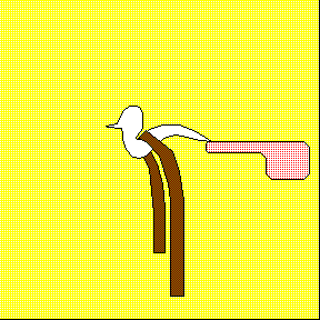
d. Hold your belt up with an otherwise unstable plastic bird.
e. A dumbbell with unequal masses on the end of a rod is suspended by s string to locate the center of mass. The dumbbell can then be tossed across the lecture hall to show that the center of mass follows a parabola, even though the ends are flying around. The center of mass is marked with phosphorescent paint which can be activated by ultraviolet light. Then in total darkness the students can see the dimly marked center of mass flying across the room in a parabola.
This oloid is composed of two circular disks which roll in such a way that the center of gravity stays constant.
If a series of identical rectangular blocks is stacked out at their balancing points from the top down, the top block can stick out arbitrarily far. You can show with a simple center of mass calculation the total "stick-out" distance; that is, the horizontal distance from the back of the bottom block to the back of the top block is 1/2(1 + 1/2 + 1/3 + 1/4 + ...). This series grows without limit.
Many students are surprised to see the top block "sticking out in space", no part of it over the bottom block of the stack. The series above shows that this can happen with a stack of only 6 blocks. In practice at least 6 are needed, and several more to make to effect dramatic.
This graphic demonstration of stability comes from Russia. When the line of the plumb bob hanging below the center of mass falls within the base, the prism is stable. But when the extended plumb bob line falls outside the base, the prism tips over. This demonstration is similar to the Tower of Pisa [12], and the two can be used together.
"Glasnost gives us this pretty demonstration from Russia. In Russia all students are required to take 5 years of physics, and these demonstrations are used throughout Russia. However, the Russians lost the Cold War so, though it pains me to say it, perhaps it is better to watch MTV than to study physics too hard!"
A beautiful wine rack demonstrates how, for stability, the center of mass must be over the support base.
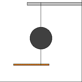
In this dramatic demonstration a massive weight is suspended by a wire from the ceiling of the lecture hall. The demonstrator stands braced against the wall, draws the mass to his nose, and releases it. If conservation of the energy holds, on the return swing the mass will stop just millimeters in front of his nose. But if conservation of energy fails,...!
The lengths of the pendulums in the corresponding lecture halls are as follows:
| PAB 1425 | 4.66 m |
| KNSY PV 1220B | 4.67 m |
 |
 |
A simple pendulum set swinging will rise to the same height on each side. If a bar interrupts its swing on one side, it will still reach the same height. The position of the bar is variable.
The ball rolling on the track will rise to the same height regardless of how the angle of the raisable side is changed

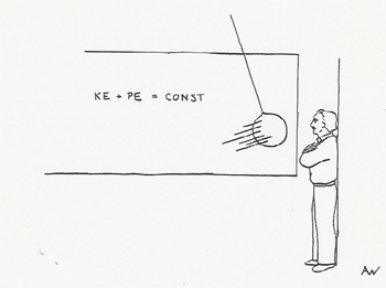
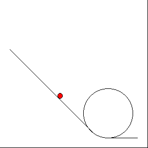
A ball is rolled down an inclined track which has a vertical 360° loop at the bottom. The rolling ball stays on the track if started from the proper height on the incline. Friction and the rotational energy of rolling must be taken into account. Note that the ball does not roll on its bottom, so it uses even more rotational energy than a rolling sphere.
 |
 |
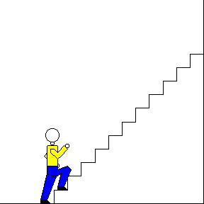
The maximum horsepower developed by a human being over a few seconds time can be measured by timing a volunteer running up the stairs in the lecture hall. If a person of weight W runs up height h in time t, then h.p. = Wh/t X 1/550 ft-lbs/sec. A person in good shape can develop one to two horsepower. It will be entertaining to the students if the professor tries it too.
Should the person be allowed a running start?
A small top, once set spinning, spins indefinitely. Can we reason that there must be some hidden, external source of energy to overcome the frictional loss of the top?

![]()
Many principles of mechanics can be nicely demonstrated with the Blackboard Mechanics Set. Among them are:
| Friction blocks on inclined planes | |
| Statics of inclined planes | |
| Levers and center of mass | |
| Vector addition of forces | |
| Pulley systems | |
| Pendula and springs |
A description book of various experiments is available.
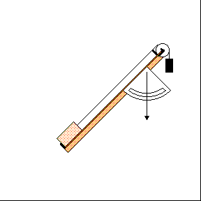
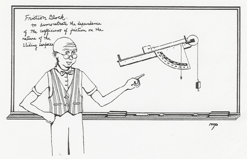
The effects of static and sliding friction are demonstrated on an inclined plane. The angle of the plane can be adjusted until the block just begins to slide. Or, a pulley, string, and weight can be used to pull the block up the plane at constant speed.
Terminal velocity is shown by dropping a ping-pong ball (with denser balls, if desired) from a platform and illuminating its fall with a strobe light. (See Three Balls Falling [7])
Please refer to: Acceleration Down an Inclined Plane (Kinematics) [13].
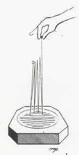
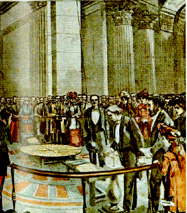
The universal gravitational constant G can be measured in class with the Cavendish balance; however, the demonstration is time consuming and delicate. A video tape of the demonstration has been prepared by Prof. C. Buchanan and Jim Abbott using time lapse photography of the optical lever readout. The tape is about seven minutes in duration and presents the students with the data of the experiment so the value of G can be calculated.
Drop a wooden ball simultaneously with a much heavier steel ball to show that they fall together. To show that the steel ball is definitely heavier, place the wooden ball in a short cup on one side of a double pan balance, and then put the steel ball in a short cup on the other side so the balance clunks down.
You might think that by this time everyone knows that a heavy object falls no faster than a light one - at least, everyone who had a high school physics course! But try asking in your Physics 10 class, "Will the heavy ball fall faster than the light ball, or the same?" You will be surprised at the variety of answers and justifications.
Then ask them about the effect of air resistance (which will probably already have come up in the discussion). To illustrate air resistance, take two sheets of paper, crumple one up into a ball, and drop them together. They have the same weight, but the flat sheet has more area "fronting the wind".
Lester Hirsch suggests a drama for jazzing up this last demonstration. Borrow the two sheets of paper from two different students. Tell them not to tear the pages out of their notebooks; you are going to return the pages. After the demonstration hand the flat sheet back to the first student, and carefully smooth out the crumpled sheet and hand it back to the second student. When he makes a face, tell the class that conversation has to start somewhere, and that he has to be one this time!
To make this demonstration somewhat more quantitative, you may wish project a slide of a wooden ball, a steel ball, and a ping-pong ball falling, photographed at 1/20 sec. intervals. (See Three Balls Falling [7])
As a final first-day demonstration, drop the "happy" and "unhappy" balls to show that objects that look identical may have very different physical properties.
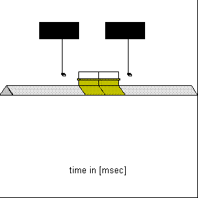
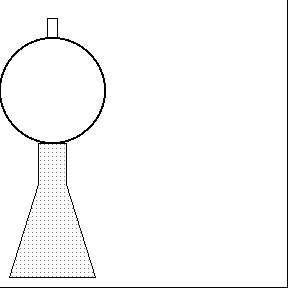
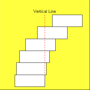
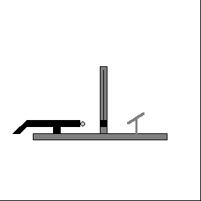
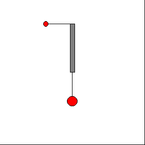
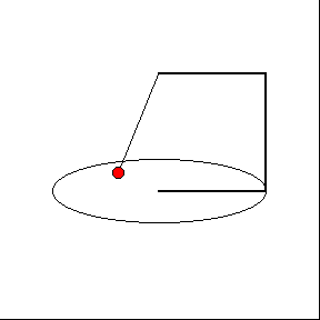
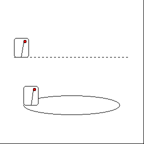
This demonstration shows that the top end of an upright rod, anchored at its bottom end, falls more rapidly than free fall. Several articles in the journals show how this effect causes a falling chimney to break about one third of the way from its bottom as it falls.
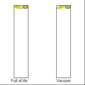
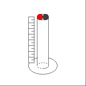
A coin and feather (or rubber cork and styrofoam chip) are inside a lucite tube 1.5 m long. When the tube is switched end for end, the rate of falling of the two objects can be compared. The tube is then evacuated to show that they fall at the same rate in a vacuum.
This experiment was repeated on the moon by Apollo 15 astronauts using a feather and a hammer. You can see the NASA video here [14]. We also have this clip on video disk which can be played in class.
A ball dropped vertically and a ball projected horizontally at the same instant hit the floor at the same instant.
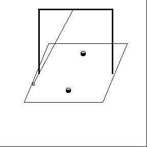
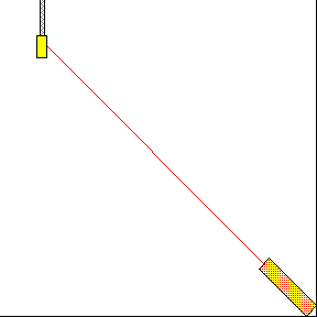
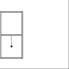
A coordinate frame in free fall in a gravitational field is truly inertial; that is, Newton's lst law is obeyed. In this demonstration a coordinate frame similar to that shown in the figure is held by an electromagnet. If the guns are fired while the frame is held, the projectiles will follow parabolic trajectories in the earth's frame and bounce off the intermediate plexiglass sheet. But if the frame is dropped, the guns firing automatically during the falling motion, the projectiles will follow straight lines in the falling frame and reach their target pockets.
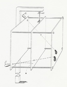
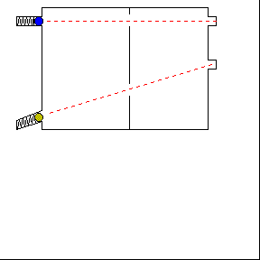
Note that this demonstration is equivalent to the Monkey and Hunter [3] demonstration.
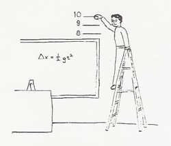
Simple Measurement of g: Heights of 6, 9, and 12 feet are marked up on lecture hall wall. Time intervals are announced by a metronome set to 80 beats/min. (Dt = 0.75 sec.) The demonstrator stands on a ladder and drops a ball from various heights on the beat of the metronome. Nine feet will be found to be the height for which the next beat is simultaneous with the ball hitting the floor. Then, g = 2h (Dt)2. This demonstration requires moderately good reaction time. A student volunteer may help. AVAILABLE ONLY IN KNUDSEN 1200

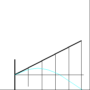
Measuring g with Sonic Basketball: In this experiment the kinematics of a basketball under the influence of gravity is studied quantitatively. The ball is thrown upward above a motion sensor to plot its position, velocity and acceleration as a function of time. (See Sonic Basketball [15])
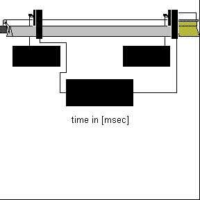
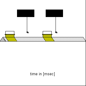
Three balls (steel, wood, and ping-pong) are suspended from a platform. As they are released, they are illuminated with a repeating strobe of known frequency. The result can be video taped with Video Point Capture. This software can be used to make measurements and analyze the motion of each ball as a function of time. A sample is shown to the right.
Two simple demonstration of weightlessness with minimal equipment are described below. (The Local Inertial Frame [16] is also a demonstration of weightlessness and the fact that Newton's First Law is obeyed in a freely falling frame.)
![]()
Clip two clothespins on the sides of a rubber band. Hold one clothespin and let the other hang down by the rubber band. The weighing of the second clothespin is represented by the stretching of the rubber band. Now release the upper clothespin. The rubber band goes slack, and the two clothespins and the rubber band fall together. The clothespin(s) are weightless when falling.
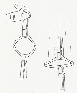
Suggested by Mr. Wizard.
![]()
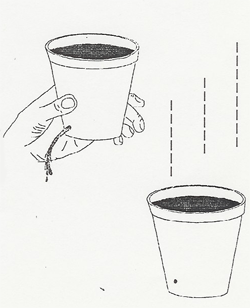
1. Punch a small hole in the side of a styrofoam cup or a 2 liter bottle near its bottom.
2. Hold your thumb over the hole as you fill the cup with water. Ask the students what will happen if you remove your thumb.
3. Remove your thumb and let the water stream out into a catch basin (a pail) on the floor.
4. Again seal the hole with your thumb and refill the cup. Ask the students if the water will stream out if you drop the cup as you remove your thumb.
5. Holding the cup as high as possible, drop the filled cup into the catch basin. The water does not stream out; the cup and water are weightless.
Suggested by Dale Bremmer.
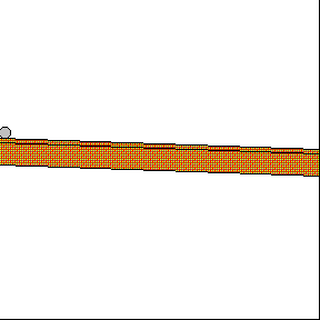
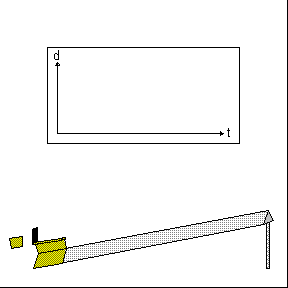
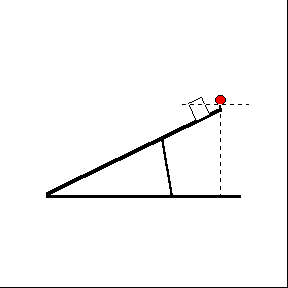
| A four meter long track is available for Galileo's "diluted gravity". Galileo argued that as the angle of incline of a track is increased, the motion of a rolling ball approaches free fall, so that the motion of the ball down the track is the same type of accelerated motion as free fall.
This device is very useful when you are discussing uniformly accelerated motion and free fall because motion is slow enough on the track so you can describe it while it is happening. For example, you can simulate a ball thrown in the air by rolling a ball up the track while discussing how its velocity decreases on the upward leg, becomes zero at the top, and increases on the downward leg. |
|
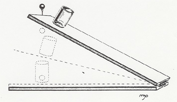
The concept of acceleration can be demonstrated by rolling a ball down the inclined plane and marking its successive positions on drafting tape pasted to the track, timing the positions with metronome beats. The simplest way to do this is to have several positions marked before the class begins and add a few more during the class demonstration, while showing the students that the ball passes all the marks at the right times. Then by measuring the distances you can show that the total distance the ball rolls increases with the square of the time.
Galileo's experiment itself is likely to be obscure to the students, since it depends on knowing that the difference of successive square integers are the odd integers. It can be performed as follows: The tape pasted to the track is marked as before, or perhaps by a student volunteer with good reaction time and coordination. The tape is then cut at the marks and pasted onto the blackboard in the form of a bar graph. The ratios of the heights 1 : 3 : 5 : 7 : 9 ... give the differences of the squares in the formula y = 1/2 at2.
A sonic ranger measures the distance to a moving object by bouncing ultrasonic sound off the object and timing the echoes. The data, taken about every 0.05 sec. is read into a computer which then plots the distance, velocity, and acceleration. The results can appear on overhead projection via the LCD screen, or in some rooms, directly on video projection. Derivatives, integrals and other manipulations of these quantities can be performed. Three typical experiments are described:
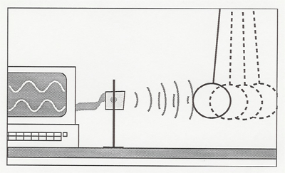
|
|
1. A cart is sent up a tilted Pasco track to roll back down. This is a good demonstration to illustrate kinematics concepts since the students can see distance, velocity, and acceleration plotted simultaneously. |
| 2. A plate is supplied which the instructor can move in various ways to again illustrate d, v, and a. Start simple; hold the plate at constant position for a few moments, move at constant velocity to a new position, and hold this new position for a few moments. Have the students predict the graphs of d,v, and a. |
|
 |
3. A pendulum is set swinging and the computer plots out the sine and cosine waves of d, v, and a. Their phase relations can be pointed out. Try reassigning the axes to plot d against v. |
Several different sonic rangers with their associated software, computers, and projection equipment are presently being tried in the classrooms. Plan on familiarizing yourself a little with the specific equipment before using it in your class.
Data Studio [17] is used with Pasco probes to demonstrate the kinematics of one-dimensional motion.
Measurements of Position, Velocity and Acceleration of Constant Linear Motion
Equipment: Computer, 2.2m Pasco track, Cart, Motion Sensor and Metal Slugs.
The above equipment is used in conjunction with Data Studio to measure and plot the position, velocity and acceleration of a Pasco cart as a function of time. During lecture the instructor can show quantitatively that at each instant the velocity and acceleration are the slopes of the line tangent to the position vs. time and the velocity vs. time curves respectively. Data Studio can also be used to obtain the average velocity and acceleration of the cart.
In the following Data Studio experiment, the Pasco track was propped up slightly on one end with adequate metal slugs to compensate for friction. Then the cart was given a slight push to achieve constant velocity. The motion sensor was used to measure and graph the cart's position as a function of time. The graph shows that the position changes linearly as a function of time. A linear fit to the position vs. time curve gives the slope to be 0.45 m/s. This constant value corresponds to the average and instantaneous velocities for this experiment. Furthermore, it is within experimental error of the mean of the velocity vs. time curve (0.46 m/s). Taking the slope of the velocity vs. time curve, we find that it is zero and therefore have zero acceleration -- also demonstrated experimentally.

Measurements of Position, Velocity and Acceleration of Nonlinear Motion
The acceleration graph is made by taking the tangential slope of the velocity vs. time curve at each point and plotting this value as a function of time. Data Studio is then used to calculate the mean of the acceleration vs. time curve where we find the value to be -9.2 m/s/s. The values obtained by the linear fit to the velocity vs. time fit from above and the mean of the selected data points of the acceleration vs. time graph are in general agreement and close to the accepted value of gravity of 9.8 m/s/s.
Instantaneous Velocity, Average Velocity, and Acceleration using the Air Track
Below is a sample set of demonstrations with an air track for illustrating these concepts using a clock (the "white clock") that measures the elapsed time for a glider to travel one meter and another clock (the "red clock") that measures the time for the 0.1m flag of the glider to pass a sensor at the end of the one meter interval.
1. First explain exactly what the clocks are measuring to the students. A transparency is available that can be projected during the demonstrations to remind them what is measuring what. Show them that the white clock measures the elapsed time for the glider to travel one meter by passing your hand through the start-gate, counting off "one thousand one, one thousand two, " for several seconds, and then passing your hand through the stop-gate. Then show them that the red clock measures the time for the glider flag to pass its sensor by blocking its gate with the glider flag, counting off several seconds, and removing the glider.
Then if the white clock reading is labeled T and the red clock reading is labeled t:
average velocity = 1 meter/T
instantaneous velocity = 0.1 meter/t
At some point you may wish to discuss how the exact instantaneous velocity is defined in terms of the calculus derivative by imagining the flag length to become smaller and smaller.
2. To check that everyone understands what the clocks are measuring, ask them, "If the track is level and I send a glider through the gates, what will be the relationship between the readings of the two clocks?" (And then do the demo!) Answer: red clock reading = 1/10 white clock reading.

3. Now use a block to tilt the track up. Ask, "The red clock should now read (greater than, less than, the same as) 1/10 the white clock. In other words, is the instantaneous velocity at the end of one meter of acceleration (greater, less, the same) as the average velocity over the one meter distance?"

4. Now use a larger mass glider. "The clock readings should be (greater, less, the same as) before?"
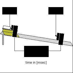
5. "At what fraction of the one meter distance does the glider attain an instantaneous velocity equal to the average velocity over the one meter? In other words, where should the red sensor be placed to get red = 1/10 white with the track tilted?" (Answer: 1/4 meter)
6. You can check the measured acceleration against the tilt of the track. If the track length is L and it is tilted height h,
acceleration = a = g sin q = gh/L
Then from the white clock, a = 2 meters/t2 a = 2 meters/T 2
and from the red clock, a = (0.1m/t)2/2m = 0.005 meters/t2
Data Studio [17] is used with Pasco probes to demonstrate the kinematics of one-dimensional motion under gravity.
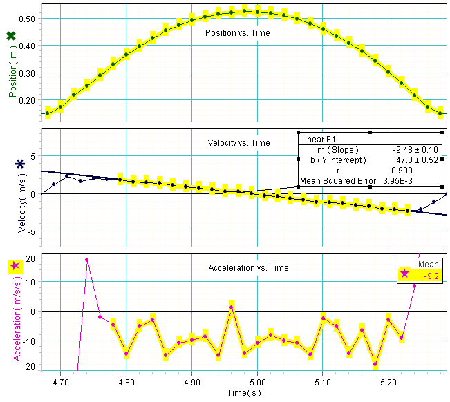
Equipment: Computer with Data Studio software, Sonic motion sensor and basketball
In this experiment the kinematics of a basketball under the influence of gravity is studied quantitatively. The ball is thrown upward above a motion sensor to plot its position, velocity and acceleration as a function of time. The graph below shows that the ball's vertical position changes quadratically as a function of time while its vertical velocity changes linearly. The tangential slope of the position curve is taken at each point to calculate the velocity vs. time plot. The ball's velocity is a maximum as the ball is first thrown upward, zero at the ball's maximum height, and negative its maximum value when the ball returns to its initial starting position. By using Data Studio's fitting algorithm, a fit to the velocity vs. time curve is found and the slope is calculated to be -9.48 m/s/s as shown.
The acceleration graph is similarly computed by taking the tangential slope of the velocity vs. time curve at each point and plotted as a function of time. The mean of the acceleration vs. time curve is calculated by Data Studio to be -9.2 m/s/s. The numbers obtained by a linear fit to the velocity vs. time plot from above and the mean of the selected data points of the acceleration vs. time graph are in general agreement and close to the accepted value of gravity of 9.8 m/s/s.
Measure the velocity of a speeding bullet using a totally inelastic collision. (See Ballistic Pendulum (Ballistics) [18])

Various balls are dropped in a transparent tube to show nearly elastic, partially inelastic, and totally inelastic collisions. The height of the bounce, marked off qualitatively on the tube, is a measure of the elasticity. A lead ball which does not bounce at all is startling.
With another piece of apparatus a small steel ball is dropped on a heavy, polished, slightly concave steel plate. The collisions are so elastic that the ball bounces dozens of times before its energy is exhausted.
With the collision ball apparatus one can show that if a moving ball collides elastically with an equal mass ball at rest, the entire kinetic energy and momentum of the first ball will be transferred to the second.
If one ball collides with a row of equal mass balls, all the kinetic energy and momentum will be transferred to the last ball.
One larger mass ball is provided to show the dependence of these results on the mass of the colliding ball.
An interesting experiment is to pull back two balls on one side and one on the other and release them simultaneously.
|
|
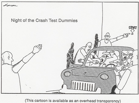
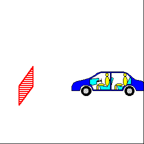
A. Understanding car crashes - It's Basic Physics, put out by the Insurance Institute for Highway Safefy and narrated by a high school physics teacher. This video is a more modern version of the Crash Test Dummies video to illustrate Newton's second law in the context of car collisions. The video uses scenes in which an egg is thrown at a brick wall and sheet to demonstrate momentum transfer and impulse. The typical running time of the appropriate segment of video is less than five minutes and the entire video is twenty-two minutes.
B. "Physics and Automobile Collisions" by Dean Zollman - This laser disc video illustrates the concepts of Newton's Laws, impulse and momentum, conversion of kinetic energy to other forms, and conservation of momentum in 2D collisions with physics narration. You may wish to watch the disk through and pick out parts appropriate for your class, or I recommend the following parts as a short general survey:
| Chapter 1 | Introduction | 38 sec |
| Chapter 2 | 1st Law, impulse and air bags | 2-1/2 min |
| Chapter 4 | Price of damage to car with and without shock absorbing bumpers | 1-1/2 min |
Elastic and inelastic collisions between carts can be demonstrated as one end of the carts are equipped with magnets and the other end with Velcro. A moving cart collides elastically with a stationary cart of equal mass using the magnetic ends. The originally stationary cart moves away with all the velocity. Elastic collisions between carts of different masses can be tried qualitatively or quantitatively with Data Studio.
Completely inelastic collisions result by colliding the Velcro ends of the carts. A carts velocity is measured before and after it has collided inelastically with another cart of equal mass. It is demonstrated that the velocity of the two carts after the collision is half the initial value.
|
Elastic Collision |
Inelastic Collision |
|---|---|
|
|
|
Explosions are demonstrated by touching the ends of two carts together and releasing an internal plunger from one of the carts.
|
Explosion |
|---|
|
|
All of the above demos may also be demonstrated with the air track at the instructor's request. The air track has an advantage over the dynamics track in that there is less friction associated with it. However, the air track has a draw-back in that it is much nosier than the dynamics track and in a lecture setting it is difficult for the instructor to be heard.
Two identical looking balls are suspended as pendula. One at a time they are lifted up to swing against a standing block. One ball easily knocks the standing block over, but the other does not. There is another pair of balls so you can show that the "happy" ball is elastic and bounces high, whereas the "unhappy" ball is totally inelastic and does not bounce. (F. Bucheit, Physics Teacher 23, 28, 1994).
Two battery-operated air cushion disks are available for demonstrating two-dimensional elastic collisions. Simply collide one disk into the other on the floor of the lecture hall.
Law of Reflection
Elastic Collision Experiments
This demonstration displays the impulsive force in a collision as a function of time using the Pasco dynamics track. The track is elevated at one end and the cart is allowed to accelerate with the force sensor connected. Data Studio [17] is used to measure and plot the force as a function of time. The momentum is just the area under this curve.
Choose two students, one heavy and one light, and stand them on the large reaction carts. When they push on each other's hands, the light student acquires a proportionally larger velocity than the heavier student.
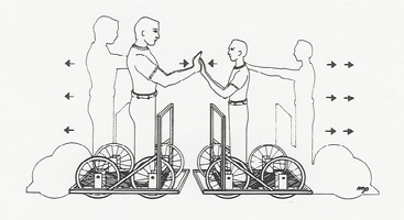
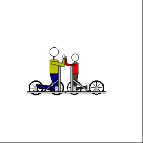
Small reaction carts illustrate the same principle on the lecture table, as do gliders on an air track connected by a compressed spring.
Ask your students to answer from:
A. heavier person
B. lighter person
C. both the same
Which person feels the greater force? Which person gets the greatest impulse? Which person undergoes the greater change in momentum? Which person undergoes the largest acceleration?
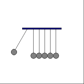
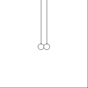
This pretty demonstration illustrates two principles: one, the period of a conical pendulum is the same as a linear pendulum; and two, all the momentum is transferred in an equal mass elastic collision.
Two identical ivory balls hang side by side from the ceiling of the lecture hall. You can illustrate the equal mass collision by pulling one out and letting it collide with the other, as in the Collision Balls [19] demonstration. Now pull both balls back, away from the class, hold one lightly with your fingers, and collide the other into it from the side. The colliding ball will stop "dead" and swing toward the class in linear pendulum motion, and the struck ball will swing around in conical pendulum motion. Since the periods of the motions are the same, the balls will again collide at the end of the swing and exchange motions. The situation will continue for some time with the balls exchanging conical and linear pendulum motion at successive collisions.
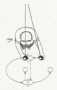
Available only in the Knudsen Lecture Halls and PAB 1425
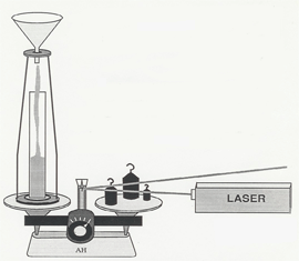
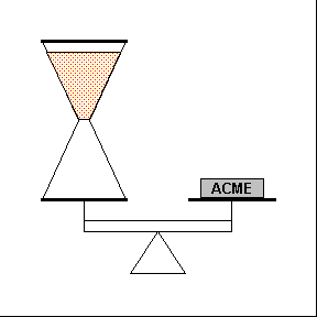
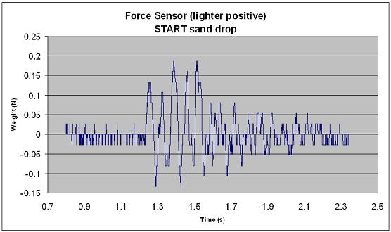
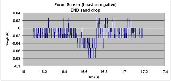
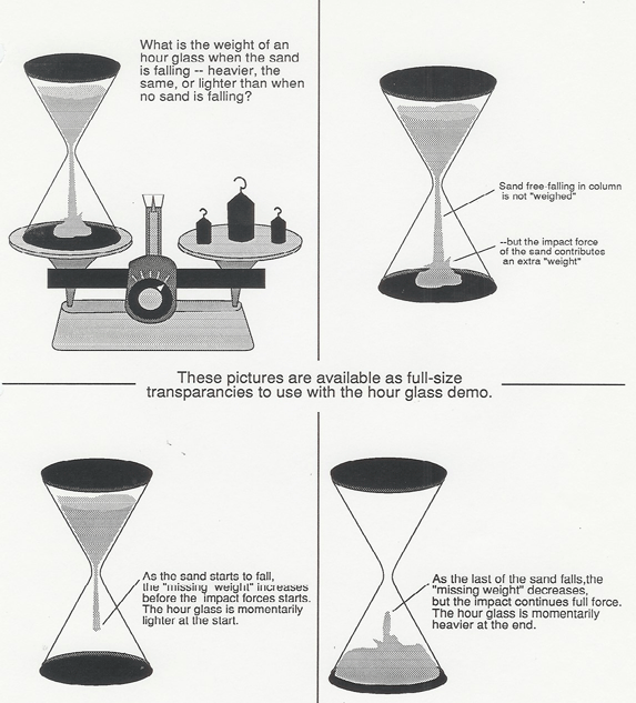
Does the weight of an hourglass change when the sand is falling? This demo shows the truth! A funnel with the sand held back by a cork and string arrangement is perched to drop sand into a glass beaker on a double pan balance. A laser bounces a beam off a small mirror attached to the pointer of the balance. When you burn the string, the sand starts falling, and the motion of the laser spot on the blackboard indicates the result. A set of transparencies to use with this demo is shown below.
| The sand in the falling column does not contribute to the weight reading. But you can easily show from Newton's Second Law in the form F = dp/dt that the extra impact force of the falling sand exactly equals the missing weight of the total falling column of sand. Thus, while the sand is falling and impacting, the weight of the hourglass is equal to its weight when no sand is falling.
But initially, as the sand starts falling, there is "missing weight" in the column before the sand hits bottom, so the hourglass grows momentarily lighter. Similarly, at the end there a few moments while the impact force remains constant as the falling column decreases to zero, so the hourglass grows momentarily heavier. The movements of the laser spot on the blackboard faithfully trace out the graph of the weight of the hourglass as a function of time. |
|
| A movie clip of the typical setup is shown on the right. Note the position of the laser spot as the sand begins to drop and as its level in the funnel changes. The graphs below were produced with data from a setup using a PASCO force sensor in place of the scale. |
 |
 |
The Paul Trap, or rotating saddle trap, is an analogy to RF-electric quadrupole ion traping.
The Loop the Loop track can be reintroduced here, and the rotational energy of the rolling ball added to the calculation of the height that the ball must be released to just make it around the track. Note that the ball does not ride on its bottom, but partly up on its sides. You will still need to add in "a couple of inches of friction." (See Loop the Loop (Energy) [20])
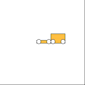
Various objects are raced down an inclined plane. There are two sets of disks, one with the mass distribution concealed and the other with the mass distribution apparent. All of the three inch disks have the same mass which you can demonstrate by placing two at a time on a double pan balance. There are also a few smaller disks available so you can demonstrate that disks of the same mass distribution but different sizes and masses roll the same.
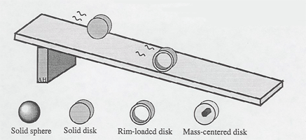
Unidentified Rolling Objects (Audience Appeal)
These demonstrations are often shown with the rolling objects above, or on the first day of class, or at physics demonstration shows, to attract interest in physics, and as an illustration scientific reasoning in working out their mechanism "How would you design a mechanical system to do this?"
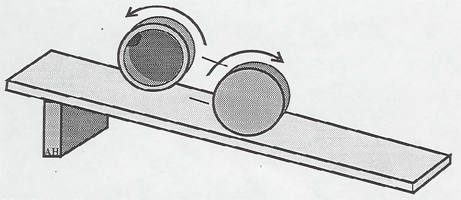
One of the "unpredictable disks", shown above, rolls down and one rolls up. The off-center weight is concealed from the audience, but can be shown after they have tried to reason out the mechanism. A "prematurely-stopping cylinder" rolls part way down and stops. A "come-back disk" rolls down some distance, and then rolls back up!
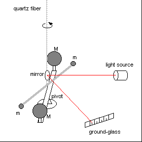
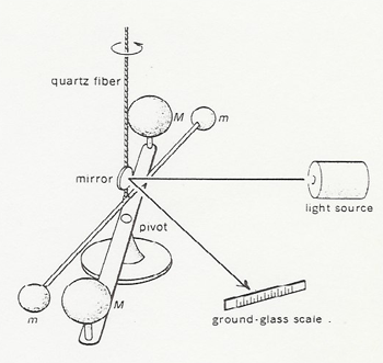
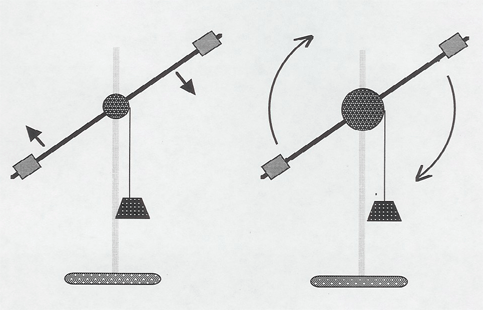
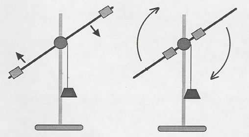
This simple device graphically illustrates the concepts of torque and rotational inertia. Movable masses are positioned on a rod which is rotationally accelerated by a falling weight. The rod arm accelerates rapidly when the masses are moved in toward the center but much more slowly when the masses are adjusted out to the ends of the rods so that the rotational inertia is large. Two devices are available so that the class can directly compare the cases of large and small rotational inertia.
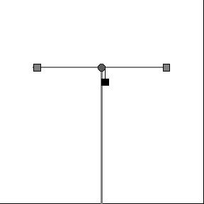
The Position of masses on rods can be varied to change the rotational inertia of a torsion pendulum. The period of the pendulum is longer for larger moments of inertia. The torque of the support wire accelerates the rotational motion more slowly when the rotational inertia is large. (See Simple Harmonic Motion [21])

Illustrates how changing the rotational inertia changes the angular velocity. (See Turntable and Weights (Angular Momentum) [4])
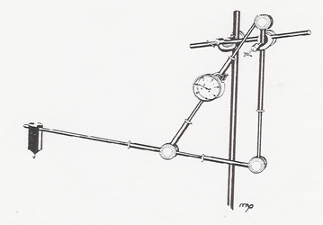
The model shown below, constructed from the strut and tie set, demonstrates the force a human biceps muscle must exert when a weight is lifted by the hand.
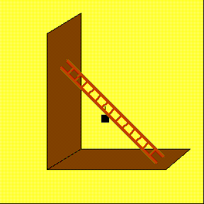
A wooden model of a ladder leaning against a wall demonstrates the angle that the ladder will slip down when weights are hung from various rungs of the ladder.
Statics of inclined planes, levers etc. can be done with the Blackboard Mechanics Set [22].
A multiple strut and brace framework can be set up on the lecture table. Force indicators (indicating newtons) are placed in the framework to show the balanced forces. The biceps muscle shown above is an example. An instruction manual showing various set-ups is available (hoisting, wall crane, roof truss, etc.).
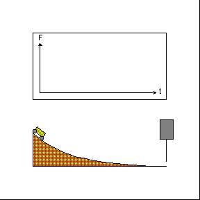
Illustrates that the torque of gravity, acting on a stick hinged at its base to the table, causes the end of the stick to accelerate faster than g. (See Falling Chimney (Gravitational Acceleration) [23])
A bicycle wheel can be mounted on the lecture table so you can illustrate the effect on acceleration of exerting forces on it at various radii and in various directions. A crescent wrench is also supplied so you can illustrate how to produce the maximum torque on the nut holding the bicycle wheel. Another simple illustration of torque is to open the door to the lab at the front of the lecture hall and push on it at various radii from the hinge with your index finger. The crumpling of your finger indicates the larger forces needed at the smaller radii.

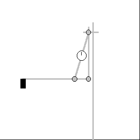
A more quantitative demonstration of torque uses the rotational acceleration device shown here [24]. The spindle is fitted with a spool of twice the radius of the shaft so the falling weight acts at 2R. Two devices are available. Adjust the weights so the rotational inertia is the same, and compare the rotational acceleration of the devices with the falling weight acting at R and 2R.

Add hanging weights at different distances to break the hold of the friction nut. It takes twice the weight at half the distance. Watch out for your foot.
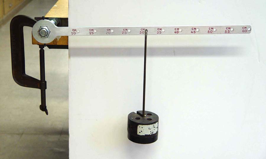
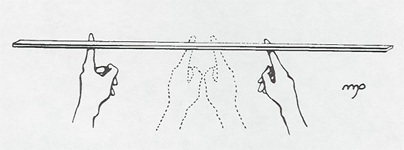
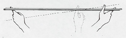
Hold a meter stick at two arbitrary places with your two index fingers. When you bring your index fingers together, they will meet at the center of the meter stick. You can show that this is a consequence of the two different friction forces resulting from the different torques exerted by your fingers. Amazingly, even if the coefficients of friction are very different, say by covering one finger with slippery chalk dust and the other with a sticky rubber glove, your fingers will still meet at the center. If a weight is placed on one end of the meter stick, the fingers will still meet at the balancing point, the center of mass.
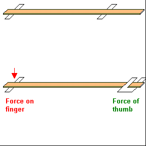
Professor Peter Schlein suggests this further demonstration of torque: Hold one end of the meter stick between your thumb and finger as shown above, and slide your index finger in from the other end. The force on your sliding finger increases from half the weight of the meter stick when your finger is at the far end to the full weight when your finger is at the center and the whole weight of the meter stick balances on one finger. As you slide your finger beyond the center towards the held end, your thumb must now exert a downward force, and the force on your sliding finger becomes extremely large. You can calculate the torques by assuming that the weight of the sections of the meter stick act at the centers of the sections.
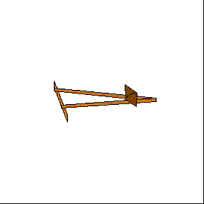
The little ball lifts the big ball - a string connecting a large and small ball passes through a tube. When the tube is whirled around, the small ball moves out, lifting the large ball.
Get both balls out - a tube is arranged so that balls fall into pockets at its ends. It is impossible to get both balls into their pockets by tilting the tube around, but if the tube is rotated, both balls move into their pockets.
Various devices fit on the variable speed rotator below:
A mass extends a spring allowing measurement of the centripetal force.
Two balls move out on rods extending a spring to measure centripetal force.
Four balls move out on semicircular wires.
Spherical shape becomes oblate when rotated.
A spinning circular chain forced off a disc by means of a stick, retains its circular shape as it rolls rapidly along the floor.
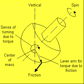
A strap of spring steel is pivoted from the center of a platform on a rotating turntable. The strap has a nail in its end so that as it falls from a standing position, it impales itself on the periphery of the platform. When the turntable is not rotating, the strap falls normally to a marked position. But when the turntable is rotating, as the strap falls the turntable continues to rotate, and the Coriolis "force" causes the strap to impale itself somewhat behind the previous mark.
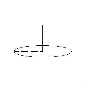
In this simple demonstration a pendulum is mounted on, and suspended over, a rotating turntable. As the turntable rotates underneath, the pendulum maintains its plane of swing.
This device consists of a tethered ball floating in a jar of glycerin. To establish its operation, hold it in front of you, and begin rapidly walking across the lecture hall. The ball will move forward in the direction of your acceleration at first, and then return to the vertical position as your velocity becomes constant. When you stop walking, the ball will move back towards you showing a deceleration.
Now that you have demonstrated that the ball moves in the direction of acceleration, place the device on a turntable and start it rotating. The ball will move inward showing the radially inward uniform circular acceleration.
Put a liter or two of water into the bucket. Slosh a little out on the floor to show there is water in the bucket. Then swing it in a circle around your head.
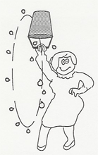
"I like to have the students 'participate' in the demonstrations, so I'll walk up into the middle of the audience to swing the bucket around. See, it's not hard! No problem at all keeping the water in! Now let see how slow I can swing it and still keep the water in!"
Swing a tray with wine glass
For a more dramatic demonstration of uniform circular motion, fill wine glass half full of water and place it on a tray with three nylon ropes connected to it. Then swing the tray around. Stopping is a bit tricky so make sure to practice beforehand. This demo really holds the students' attention and excites them - especially if the glass breaks!
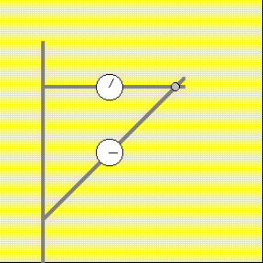
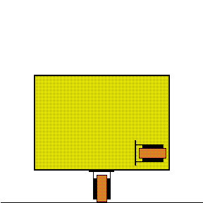
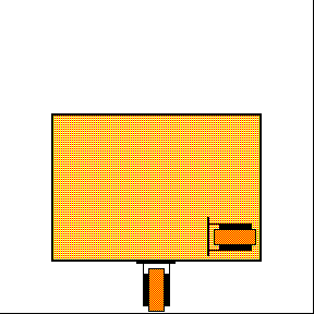
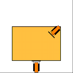
The simple set up shown below, suggested by Prof. P. Schlein, is a good illustration of the vector addition of forces. The vertical angle of the strings can be measured with a large protractor.
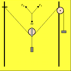
Various similar arrangements can be done with the Blackboard Mechanics Set [22].
This device operates on a view graph for the whole class to see easily. Angles are measured by the circular protractor; magnitudes of the forces by the extension of the springs via Hooke's Law.
Label the rings one through seven, starting with the first black ring beyond the last red ring. The force in grams weight as measured to the base of the cone forming the vector arrow is:
|
Ring |
Force |
| 1 | - |
| 2 | 50 gms |
| 3 | 85 |
| 4 | 120 |
| 5 | 155 |
| 6 | 190 |
| 7 | 225 |
Force in gms. wt. = 35 X ring # - 20
A good illustration and exercise in adding vectors is provided by a sailboat. The situations of "running with the wind", sailing crosswind, and sailing "close to the wind" are well reviewed in Epstein's Thinking Physics, 2nd Ed., pp 32 - 37. All of these examples can be demonstrated on the air track using a glider with sail and an electric fan to produce the wind. You can actually get the glider to move forward about 45 degrees into the wind.

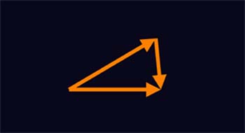
Vector Addition
This apparatus consists of a platform that rolls along the lecture table, and some toy bulldozers or carts to roll on it. You can push the rolling platform with your hand or let a bulldozer push it. The angle between the motions is completely adjustable. The demonstration can be shown in several versions:
A. As a qualitative illustration, let the bulldozers move and sketch the resulting vectors on the blackboard.
 |
 |
B. To illustrate the path of a boat crossing a river, set the bulldozer rolling on the platform at slight back angle and mark a direction perpendicular to the platform motion on the lecture table with blocks. With the correct adjustments, the bulldozer moving on the platform will be seen to cross the shortest distance perpendicular to the "current".
C. The apparatus is set up on butcher paper, the initial positions of the bulldozers marked, and their final positions marked after the bulldozers have moved. Then the butcher paper can be taped up on the blackboard and the vectors sketched in.
D. In an elaborate demonstration, apparatus is set up as in the illustration above with a bulldozer pushing a blinky while a picture is taken of three blinky tracks as first one bulldozer moves, then the other, and then both. The picture is developed in ten seconds and projected on the screen so the students can see the three blinky tracks.
Magnetic arrows are available which can be stuck on the blackboard. Arrows come in various lengths and can be placed tip to tail to demonstrate vector addition. A protractor and ruler are also available to measure the angle and length of the resultant vector.
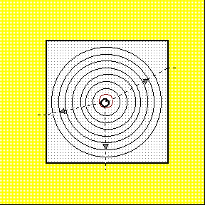
A simple demonstration of a radian. Is shows the relation between the radius and the section of circumference of a circle. A straight radius is lifted off and placed on the curve of the circumference. The angle bounded is one radian.
Data Studio is a data acquisition, display and analysis program. The software works with PASCO sensors and interfaces to collect and analyze data in real time. UCLA Physics and Astronomy Lecture Demonstrations has developed numerous experiments for use with undergraduate lectures to demonstrate physics concepts. Some of the concepts that can be shown include the following:
The relation between position, velocity and acceleration (p,v,a plots).
Conservation of momentum and energy.
Heat engines (PV and TS plots).
The relation between pressure and temperature at constant volume (PT at constant V plots).

Links:
[1] https://demoweb.physics.ucla.edu/node/427
[2] https://demoweb.physics.ucla.edu/node/265
[3] https://demoweb.physics.ucla.edu/node/387
[4] https://demoweb.physics.ucla.edu/node/380
[5] https://demoweb.physics.ucla.edu/node/381
[6] https://demoweb.physics.ucla.edu/node/413
[7] https://demoweb.physics.ucla.edu/node/402
[8] https://demoweb.physics.ucla.edu/node/410
[9] https://demoweb.physics.ucla.edu/node/378
[10] https://demoweb.physics.ucla.edu/node/386
[11] https://www.youtube.com/watch?v=92PnUomscGU
[12] https://demoweb.physics.ucla.edu/node/391
[13] https://demoweb.physics.ucla.edu/node/407
[14] https://demoweb.physics.ucla.edu/sites/default/files/demomanual/mechanics/gravitational_acceleration/astronaut.mov
[15] https://demoweb.physics.ucla.edu/node/404
[16] https://demoweb.physics.ucla.edu/node/411
[17] https://demoweb.physics.ucla.edu/node/416
[18] https://demoweb.physics.ucla.edu/node/383
[19] https://demoweb.physics.ucla.edu/node/276
[20] https://demoweb.physics.ucla.edu/node/397
[21] https://demoweb.physics.ucla.edu/node/261
[22] https://demoweb.physics.ucla.edu/node/400
[23] https://demoweb.physics.ucla.edu/node/412
[24] https://demoweb.physics.ucla.edu/node/429
[25] http://ephysics.physics.ucla.edu/newkin/html/position_velocity_ship.htm