
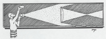
The kit has been improved with magnetic clamping to the blackboard and a multiple ray projector. Most of the principles of geometrical optics can be nicely demonstrated with this kit
We have a light which magnetically clamps to the blackboard and projects five parallel rays. This dramatically shows convergence and divergence of rays in lenses and mirrors.
The Lenses and Mirrors applet below can be used as an online demonstration.
Physlet by Wolfgang Christian webPhysics, Davidson College [1]
Instructions on how to use the animation:
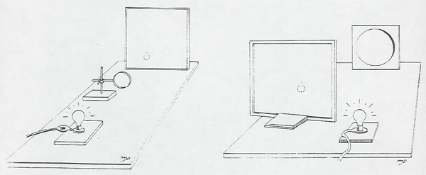
The setups below demonstrate the formation of the real, inverted image by a lens or mirror.
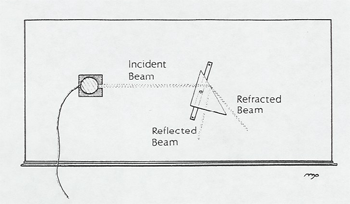
The laser is used in many demonstrations, but the students are delighted with the device itself.
First make a spot on the side wall and then catch it on your hand to show that the beam will not burn a hole through your hand. A short discussion of the dangers of looking down the beam is appropriate at this point.
Then place the laser on the table so the beam hits the side wall, walk along to the middle of the beam, and clap erasers over it so the pencil-like beam is outlined in falling chalk dust. We also have fog-in-a-can available for outlining the laser beam. (This is very effective.)
A similar stunning demonstration for a small group to gather around is to ask for a volunteer with a diamond ring. Beam the laser into the diamond, and clap chalk dust over it. The many tiny beams emerging from the diamond are very beautiful. The beam pattern can be used to "fingerprint" the diamond uniquely.
Another short demonstration is to place a human hair in the beam. From the resulting diffraction pattern and the wavelength of the laser, you can calculate the diameter of the hair.
A Metrologic publication "101 Ways to Use a Laser" is available.
A strongly converging lens shows obvious chromatic aberration. Another strongly converging lens is arranged so that the outer half of its diameter can be blocked (lens "stopped down"), or the inner half can be blocked (leaving an annular ring lens). The two arrangements have different focal lengths showing spherical aberration.
Other types of aberrations can be arranged with various lenses and mirrors.
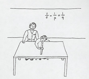
The near (pn) and far (pf) focusing distances of a student volunteer and his/her glasses prescription computed. The impressive thing about this demonstration is that you pay the optometrist $25 for the same service!
To measure the near and far focusing distances without danger of poking a ruler in the volunteer's eye, lay the ruler or meter stick on a lecture table with it's end at the edge of the table.. A volunteer should be chosen who is nearsighted without serious astigmatism (glasses diverging and rotationally symmetric). The volunteer is seated at the table and places his eye at the end of the ruler. Using a 3 X 5 card with fine print, the volunteer quickly determines the nearest and furthest distance he can focus clearly on it.
Without justifying the steps, the calculation goes as follows:
q = optical path length of eyeball, this is fixed for a particular individual and is unknown.
ff = focal length of eye lens and cornea with muscles relaxed.
fn = focal length of eye lens and cornea with muscles max contracted.
fg = focal length of glasses (to be determined).
Then,
1/ff = 1/q + 1/pf
The glasses should correct the far point to infinity, so
1/ff + 1/fg= 1/q + 1/infinity
Subtracting,
pg = 1/fg = -1/pf
Will the "patient" be able to read with these glasses on? Compute his near focusing distance pn' with glasses on.
1/fg + 1/fn = 1/q + 1/pn
Thus,
1/pn' = 1/fg + 1/pn
The quantity pn' should be less than 25 cm for easy reading. Otherwise the "patient" will need reading glasses or bifocals.
The power of accommodation can also be computed.
POA = pn - pf = 1/fn - 1/ff = 1/pn - 1/pf
In the farsighted case the person's far point will be beyond infinity, so to speak; that is, his eye will not focus at any finite distance, when relaxed. To handle this case, introduce a converging lens of known power pc = 1/fc at the person's eye. (The power should be chosen to bring his far point in to an easily measured distance, half a meter or less.) Then measure the near and far point through the converging lens. The equations are now
1/ff + 1/fc = 1/q + 1/pf
and
1/fn + 1/fc = 1/q + 1/pn
and fg can be computed as before from the known value of fc.
This demonstration was inspired by Chapter 26 of College Physics by Franklin Miller, Jr. (Harcourt Brace Jovanovich, New York, 1977).
(Art Huffman, A.J.P. 48, 309 (1980))
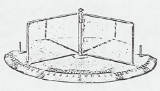
A peanut bulb is placed between two large folding mirrors attached to eachother with a hinge. By changing the angle between the mirrors, the number of images change.
A set of color filters can be projected in a triangular overlapping circle pattern. Filters available are red, blue, green, and minus red, minus blue, and minus green.
The Rav'n light is a small pulsing light that looks white. When swung around on a string you can see that it is made up of only red, green, and blue pulses.
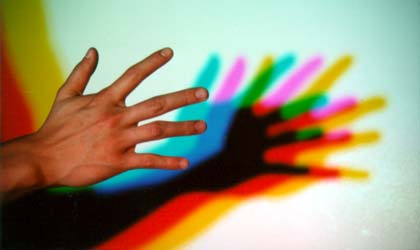
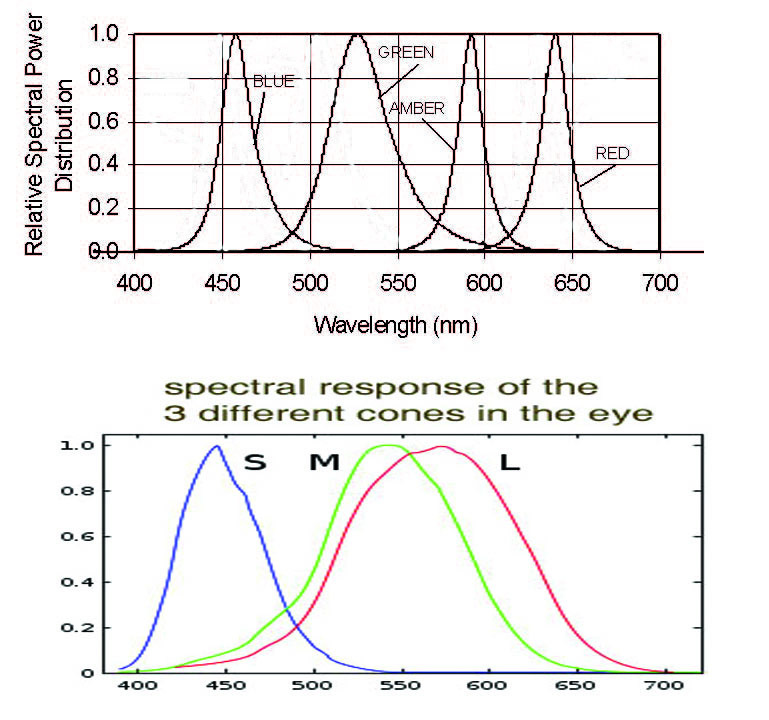
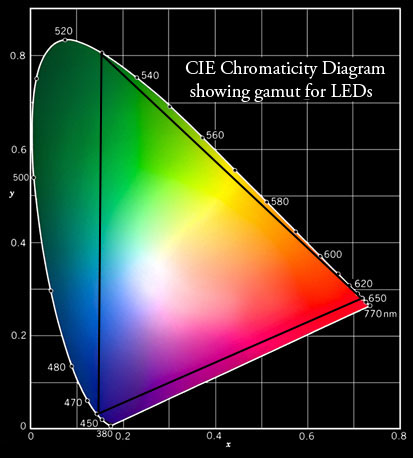
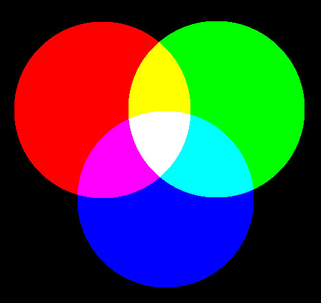
There is a new set of red, green and blue leds which can be projected into overlapping circles. The intensity of each light can be adjusted to some extent to make any color in the overlapping region. An amber led is also available and can be compared to a mixture of red and green. This can be used to discuss how the eyes see color. Why for instance, do red and green light, with no wavelengths in the yellow spectral region, give the sensation of yellow? The answers can be found in the sensitivity of the three types of cones in the eye. Sample led spectra, cone sensitivity, and the CIE diagram are below. The CIE diagram can be used to describe the gamut of any display device. For more info go here. [2]
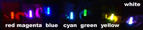
Also available are hand-held color mixers. One device has a tricolor red, blue and green LED with three switches. By pressing two of the three switches, the secondary or negative colors are made and by pressing all three at the same time we get white light.
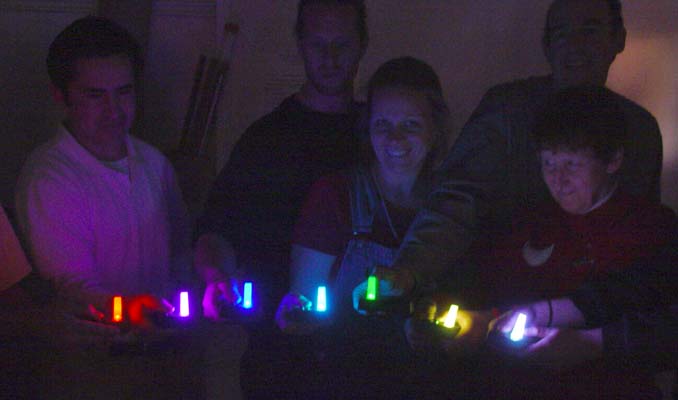
Participants at a workshop show the seven possible colors after making this little color mixer with a tricolor led. This is similar to controlling a single pixel of a 3 bit RGB display. Black is the eigth color.
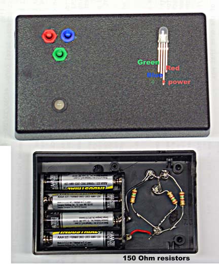
The tri color led can be found here [3].
Color Algebra
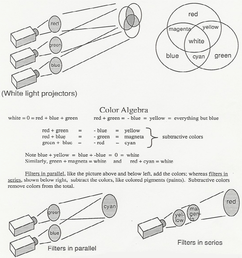
Light from red, green and blue LEDs is projected into overlapping circles. The intensity of each LED light can be adjusted to make white or other colors in the overlapping region.
Spectral colors are characterized by the wavelength of the electromagnetic radiation. The shortest wavelength that can be seen by the eye is 380 nm violet. The longest wavelength which can be seen is 770 nm red. The wavelengths of the light produced by the red, green, and blue LEDs is shown in the top graph, along with that of an amber LED.
One interesting thing to note is that the spectrum of the amber LED does not overlap very much with the spectrum of the red and green LED. The light from the red and green LEDs does not contain any amber wavelengths around 590 nm, yet we see the color amber when we mix red and green light. Why is this?
The answer can be found in the sensitivity of the three types of cones in most peoples eyes (see the second graph). These are sensitive to short, medium, and long wavelengths which roughly correspond to blue, green and red light. Amber light at 590 nm, excites both the green and red cones. We can fool the brain into seeing amber, by supplying the right amount of red and green stimulation. That's why color mixing works. However, everyone's eyes are different. Some people only have two types of cones and have some color blindness. Some reportedly have four types. The ratio of red to green cones varies widely from person to person. The ratio of red and green light to match the spectral 590 nm amber also varies from person to person. We don't all see the same colors.
RGB display devices like TV's and monitors project red, green, and blue light to produce the sensation of all the colors. The CIE diagram shows all the colors that can be perceived by the eye/brain. The spectral colors lie on the white curve identified by wavelength and all the various mixtures appear inside. The color gamut of a display device is that part of the full range of colors that the device can reproduce. The color gamut of the red, green and blue LEDs is the area inside the triangle with vertices at the wavelengths of the LEDs. Colors outside the triangle cannot be matched by mixing the light of those LEDs. How close can we get to spectral amber?
Printer inks, paints, and filters use subtractive rather than additive colors. Instead of red, green, blue, printer primaries are usually cyan, magenta, yellow, and black. Printers also have a color gamut and can't reproduce colors outside their gamut. This can lead to problems when the display gamut doesn't match the printer gamut. Colors that can be seen on the screen can't be printed.
Real: The "UFO shaped Optical Illusion" produces a stunningly real looking 3D image of a small object placed inside it. A laser can be shined right on the image, demonstrating optical reciprocity. The device consists of two parabolic mirrors, each at the focus of the other. The object is placed on the lower mirror at the focus of the upper mirror. Beams from the object diverge to the upper mirror and are reflected parallel down to the lower mirror, whence they are converged up through a hole in the upper mirror to form the image.
Virtual: In this impressive demonstration the virtual image of the flame of a concealed candle in a sheet of plate glass appears over an unlit candle wick. You can put your finger in the "flame" and grimace, or pour water over it and not put it out
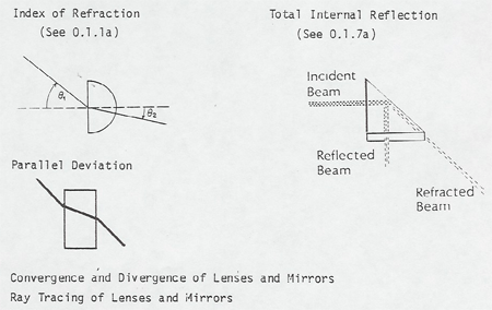
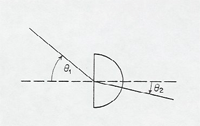
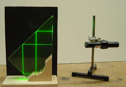
Index of Refraction: With the Blackboard or Whiteboard Optics semicircle piece you can measure the index of refraction of the lucite material directly with Snell's Law This will be a useful value later if you plan to use the rectangular block for parallel deviation or the prism for total internal reflection. Then you can predict and check results from your measured value of n. See Blackboard Optics [4] and Measuring a Glasses Prescription [5].
A beam of light is passed through a cell containing precipitated sulfur and then focused on a screen. As the sulfur precipitates, the transmitted beam becomes redder as more and more of the blue light is scattered out of the beam to the sides. The side scattered light can be shown to be polarized.
Links:
[1] http://webphysics.davidson.edu/Applets/Applets.html
[2] https://demoweb.physics.ucla.edu/node/371
[3] http://store.nichia.com/index.asp?PageAction=VIEWPROD&ProdID=52
[4] https://demoweb.physics.ucla.edu/node/362
[5] https://demoweb.physics.ucla.edu/node/367
[6] https://demoweb.physics.ucla.edu/node/360