
Calcite crystals are available to show the double image of birefringence. One is mounted on a slide projector to produce two circular images from a single hole. As a Polaroid sheet analyzer or the crystal itself is rotated the "extraordinary" and "ordinary" images come in and out of view.
A model of the molecular structure of calcite is also available.
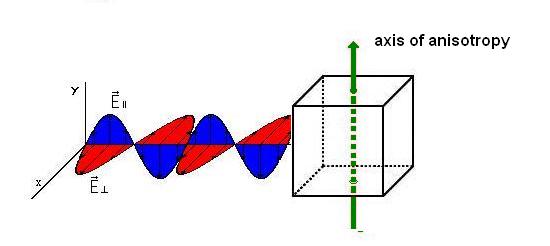
The diagram below shows light entering a birefringent material. Only the E-field is shown, resolved into components along the X- and Y-axis. Upon entering the material light is split into two rays, the ordinary and extraordinary ray, traveling at different velocities. The o-ray and e-ray are plane-polarized along mutually perpendicular directions. The o-ray has polarization perpendicular to the axis of anisotropy and therefore experiences a different index of refraction than the e-ray which has polarization parallel to the axis of anisotropy. The difference in the refraction indices is greatest when the light ray is traveling perpendicular to the axis of anisotropy as portrayed in the diagram. There is an instructive simulation on birefringence available through the website for the PLC project [1] at Case Western Reserve University.
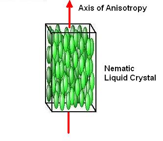
A schematic of a birefringent material showing the axis of anisotropy.
Brewster's angle is nicely demonstrated with the apparatus shown. With the polarizer on the projector horizontal, the reflected beam will be completely extinguished as the glass plate is rotated to Brewster's angle. You can now rotate the polarizer to show polarization of the reflected beam.
A polarizer and analyzer above and below the bulb end of the cryophorus are crossed to extinguish light transmission and dry ice plus alcohol to increase thermal contact are introduced into the cup end. Rapid evaporation of the water inside the bulb end causes a raft of ice to form. The first time the ice freezes, in about three minutes, many small crystals form at once and jump into view on the overhead screen. The dry ice is now removed, the projector focused carefully, and the cryophorus warmed by hand until the ice melts and the last crystal is just disappearing from the overhead screen. There will still be a few ice crystals left at this point as they melt thinner than the half-wave plate thickness. Dry ice is immediately reintroduced, and in thirty seconds or so beautiful large ice crystals will be seen to grow from the remaining seed crystals, accompanied by Ooh's and Aah's from the class. The demonstration can be repeated several times.
Shown by analyzing light scattered by slide projector. See Sunset Colors from Scattering [2].
Polaroid sheets can be crossed on the overhead projector to show extinction. A third sheet, inserted at 45deg to the other two, will permit 1/8 of the original light to be transmitted. How does inserting a sheet, which can only absorb light, cause more light to be transmitted?
Links:
[1] http://plc.cwru.edu/tutorial/enhanced/lab/lab.htm
[2] https://demoweb.physics.ucla.edu/node/369