
Small ultrasonic piezoelectric transducers serve as transmitters or receivers for centimeter sound waves. A simple setup with two transmitters hooked to the same signal generator produces a very nice interference pattern read out on an oscilloscope. (See Acoustical Interference [1])
A hollow prism filled with carbon disulphide will disperse white light into its component colors. Other glass and lucite prisms are available, but their dispersion is not as great as CS2.
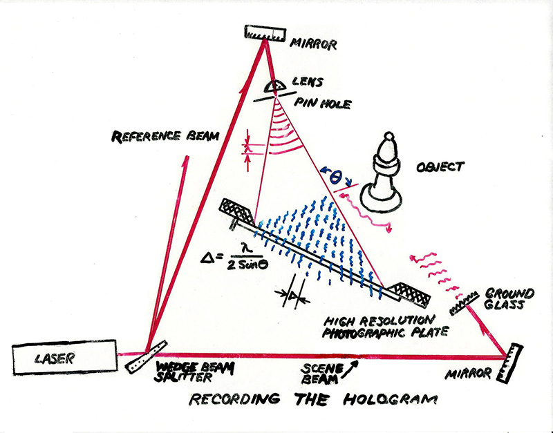
A laser transmission hologram can be set up for individual viewing by the students. One is of a magnifying glass in front of a watch. You can look behind the magnifying glass and see the watch, or look through it and move your eye in and out to see the focus change.
A classic white light "multiplex" image of a woman blowing a kiss is available as well as other reflection type holograms of a microscope, skulls, etc.
A small interferometer can be demonstrated in class. This is useful when discussing relativity besides the optics application. The fringe pattern can be projected onto the overhead screen, and you can measure the wavelength of the laser light by advancing one of the mirrors with a micrometer screw and counting fringes.
In a very similar setup reflected light from a Newton's rings apparatus is focused on the rear projection screen and the circular colored fringes observed.
Our large ripple tank projects onto the overhead screen to demonstrate reflection, diffraction, interference, etc.
Also available is an PHET applet [2] that nicely demonstrates the interference and diffraction of waves.
A laser beam is arranged to pass through the slits and be reflected onto the overhead screen. Standard demonstrations are single slit diffraction, double slit interference, and diffraction from a circular opening. Two lasers are arranged so that single and multiple slits can be shown simultaneously, one pattern above the other.
We have precision slits etched in metal foil. The slit widths and spacings are marked. The most useful single and double slits have a width of .04 mm. The double slit spacings are .125, .250, and .5 mm. There is also 3, 4, and 5 slits with the same width (0.04 mm) and spacings of .125 mm.
Hair, CD's and DVD's can be used as diffraction gratings. Simple measurements of the first maximum gives the track spacing. Comparing the pattern from CD's and DVD's gives the ratio of the track spacing for the higher density DVD.
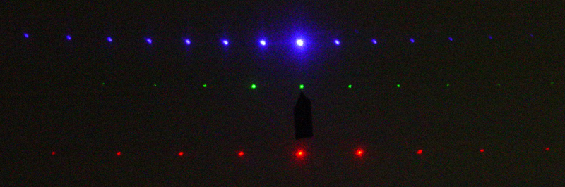
The diffration pattern can be observed with both a red and a green laser simultaneously to show the effect of wavelength. The red laser wavelength is 0.6328 micron and the green laser is 0.532 micron.
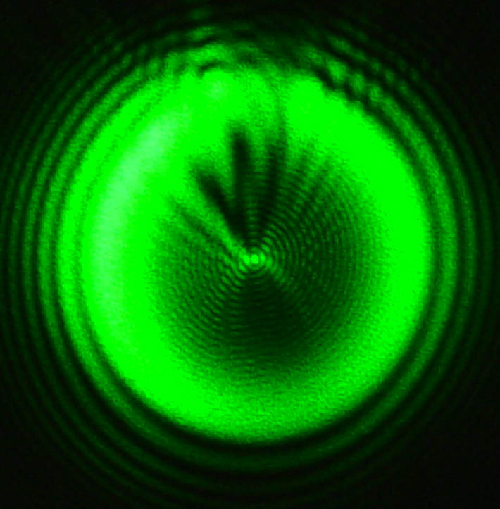
A small ball bearing in a laser beam can show the Arago bright spot (or Poisson spot) in the center of the shadow as seen below. This image also shows the fine structure in the shadow. This demo is best when the students can come right up to the shadow image and look at it directly.
The Cornell plate, diagrammed below can also be used for these demonstrations. It is clipped to a special stand so that successive slits in each column can be brought into the laser beam by adjusting a rack and pinion knob.
Column (a) Successively narrower single slits
Column (e) Successively wider double slits
Column (b) Single slit starts narrow, becomes wider,
becomes double slit, becomes narrower.Column (d) Go from one slit to two slits to three to four to ten to show sharpening
of the fringe maxima.
The Cornell plate was originally designed to be used (and can still be used) with the individual eye to view a straight filament bulb.
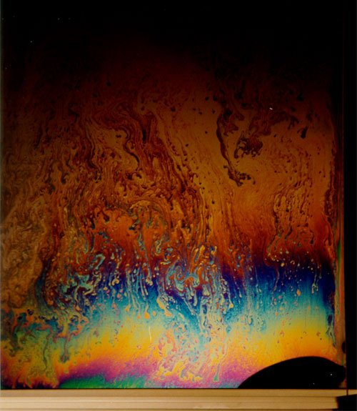
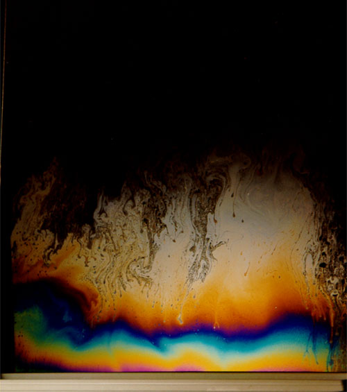
In this pretty demonstration light reflected from a soap film is focused on a rear projection screen. Gravity makes the soap film thicker at the bottom, so the image is a series of colored fringes produced by interference between the light reflected from the front and back surfaces of the film. As the water evaporates, the soap film becomes thinner, and a black area appears at the top of the film (bottom of the screen, if using a lens). When it becomes thinner than 1/4 (lambda/n), it represents destructive interference owing to the 180° phase change at the outside surface. The images below show this effect. (The phase changes at free and fixed ends can be demonstrated with the Bell Wave Machine [3].)

Links:
[1] https://demoweb.physics.ucla.edu/node/52
[2] https://phet.colorado.edu/en/simulation/legacy/wave-interference
[3] https://demoweb.physics.ucla.edu/node/281