
A light bulb with a large curly filament is connected alternately to 110 V AC and DC sources. A magnet is brought near the bulb. The filament under goes a steady deflection in the case of DC, but vibrates impressively in the case of AC.
The difference can be further illustrated by hooking a large inductance or capacitance in series with the bulb. The inductance "passes" DC but "blocks" AC, whereas the capacitance "blocks" DC but "passes" AC. See Capacitors and Inductors [1] for details.
Here is another demonstration of AC: A bicolor LED is connected directly to the 110V AC line. When the instructor swings the LED around her/his head, the light flashes green then red, showing that the LED is lit for only one half of the AC cycle. The same LED can be connected to a DC source, then the LED has one polarity, either red or green.
- This is a circuit that looks very much like the canonical series circuit, but the switches and lights don't do what's expected. There has to be a deeper level of knowledge and understanding to figure it out.
Here's the apparent circuit.
The puzzle is, what components can be added to this circuit to give the observed behaviour? One could think about the effects of common components such as resistors, inductors, capacitors, diodes, transistors, etc. I can tell you it doesn't involve magnets or radio frequency transmitters. If you figured it out, check the solution. If you haven't, I can give you three hints:
Diodes provide the coding and decoding by phase of the AC current. A diode is put in parallel with the each switch and light.
A diode is a uni-directional valve. It will let current pass in one direction but not the other. A diode in this direction  will let positive current pass from left to right but will block negative current. From the other direction negative current will pass but positive current will be blocked. Diodes are marked with the vertical bar to indicate the direction.
At the switches:
When the switch is open, all current is forced to flow through the diode. One switch diode blocks positive current and one blocks negative current. If both switches are open, all current is blocked and no lights light up.
When a switch is closed, the diode is bypassed, shorted out, and both polarities can pass through the switch. Otherwise, each diode blocks one polarity.
At the lights:
The lights act as resistors and will pass both polarities. Here, each diode acts as a short circuit for one polarity, and acts to bypass the light. The other polarity, blocked by the diode, is forced through the lamp and causes it to glow.
With two switches there are 4 possibilities:
open open 0 current
open closed + current
closed open - current
closed closed + and - current
One light turns on from the + current and one from the - current.
Here's a circuit where the lights are replaced with led's. See if you can figure out what should happen.
Various low-pass and high-pass RC and RL filters can be constructed to your taste. The Pasco Waveform Analyzer has tunable low, high, and band-pass filters built into its circuitry so the harmonics of a square, sawtooth, or other complex waveform as from the Fourier Synthesizer, can be analyzed.
A simple RC circuit will integrate or differentiate waveforms:
(Of course, the derivative and integral of a sine wave is the leading and lagging cosine wave; these are just the normal 90° phase shifts.) The circuit below integrates.
The resistance R is made large and the capacitative reactance Xc is made small by using a large C and/or a large W. Then the current into the circuit is set by R and proportional to Vin. The capacitor stores and integrates the charge.
To differentiate the circuit is wired as below:
We arrange for nearly all the input voltage to drop across the capacitor (Vc >> Vout ) by making R small and Xc large using a small C and/or w Thus the voltage drop across R measures i without disturbing Vc.
The circuit looks essentially like a capacitor to the input. The current is set by C and the small R is placed in series to sense it. RL circuits will perform the same operations.
A relaxation oscillator circuit as seen in RC Time Constant [3] demonstrates the RC time constant by a flashing neon bulb.
With a square wave input the voltage across the capacitor shows the exponential decay on an oscilloscope.
You could roughly measure the time constant t c= RC from the oscilloscope trace. With a similar circuit for RL you could estimate the time constant tL = L/R. These circuits are analyzed and their oscilloscope traces depicted in Halliday and Resnick, Part 2; for RC, Section 32-8, pp 705 -709; and for RL in Section 36-3, pp 798 - 801. As discussed in E.7.5, the same circuits will integrate and differentiate waveforms.
A simple, graphic demonstration of a series RLC circuit is to use a small light bulb for the R. Then you can tune through resonance and see the bulb's brightness reach a maximum, or you can set the frequency a little below resonance and insert an iron core into the inductor and see the bulb's brightness go through a maximum.
A parallel RLC circuit is set up so it can be driven with a signal generator and its resonance observed on an oscilloscope. The R (and thus Q), L and C are all variable. Alternatively, the circuit can be pulsed and the exponentially damped oscillations observed on a scope.
(The small input and output capacitors serve to isolate the RLC circuit.)
If the signal generator is replaced with a sweep frequency generator, the oscilloscope can be caused to actually draw the resonance curve.
The sweep generator repeatedly sweeps across a band of frequencies including the resonance. The output of the RLC circuit is then amplitude modulated by the resonance curve. Its average is still zero, but after passing through the diode which acts as a detector and being smoothed by the capacitor the final result is the response curve of the RLC circuit as a function of frequency. You can vary the position of the peak of the curve by changing C or L, or you can vary the width of the curve (Q) by varying R.
You may become confused when you try to use the dual trace feature of the scope, for example, to demonstrate the 90° phase shift of a capacitor, unless you understand how the leads are grounded.
One side of both scope leads is grounded, and one side of the signal generator is grounded. This prevents you from hooking up the naive circuit below to show the 90° phase shift.
You can "fake" the situation by using a small resistor (1000W) as shown below.
The voltage across the resistor alone shows the phase of the current through the capacitor. The voltage across both is the voltage across the capacitor -- mostly, if R<< Xc. Then these two voltages are almost
90° out of phase. For a capacitor, then, you want to use a low frequency so Xc is large.- In the similar circuit with an inductor you would use an high frequency so XL is large.
But the simplest way of demonstrating the same phase shift is use a two prong adaptor on the plug of the signal generator. Then the signal generator ground is floating, and the circuit can be hooked up as below.
You are reading the voltages across the resistor and capacitor in the opposite directions, so press the invert button on channel 2 of the scope to show properly that the voltage lags the current in a capacitor.
Adjust the two signals to have the same amplitude, and then turn the sweep rate knob counter-clockwise to the X-Y position to display the 90° phase shift in the form of a perfect circle.
The similar situation with an inductor is well shown with L = 50 mH and R = l0K.
The voltage in the circuit above is adjusted so that the light bulb glows dimly. When the switch is opened, the bulb will flash much brighter momentarily as the magnetic field collapses around the inductor.
A neon bulb can be substituted and the voltage adjusted far below threshhold. The neon bulb will flash when the switch is opened, showing that the back EMF is much larger than the steady voltage.
The circuit can be arranged to produce a large spark when the switch is opened.
Impressive sparks are produced when various capacitors are discharged.
A 4000 F capacitor is charged to 150 V. It can then be carried close to the class and snapped in front of them. This is guaranteed to wake up the sleepers!
A Leyden jar is charged to 50,000 V with a Van de Graaff generator. It can even be disassembled and the outer and inner cans touched together, and then reassembled (carefully! ). Now, when the outer and inner cans are bridged by a discharge wand, a half-inch spark jumps. (See E.1.5 [4]).
 |
 |
Wire exploder: A 175 F capacitor is charged to 4000 V and discharged through a small wire. The wire vaporizes with a large bang and flash. This demonstration is dangerous and must be performed by a lecture demonstration staff member.
Sources of 110 V AC and DC are fed alternately to a standard incandescent bulb in series with a large inductance or capacitance. The capacitance will "pass"AC but "block" DC, whereas the inductance will "block" AC and "pass" DC. With the AC supply, if an iron core is lowered into the inductor coil, increasing its inductance, the light bulb becomes dramatically dimmer, illustrating a theater light dimmer circuit.
 |
 |
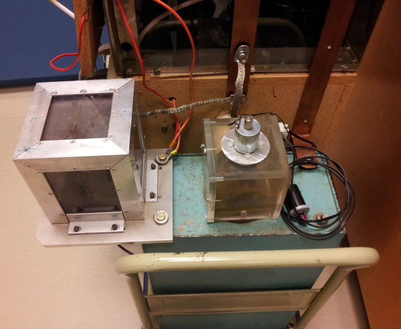
This apparatus is based on a fusion energy device called a theta pinch. A large capacitor is charged and a high current switch discharges it through a coil with just a few turns. The "theta" current in the coil produces a radial pinching effect on any conductor inside the coil.
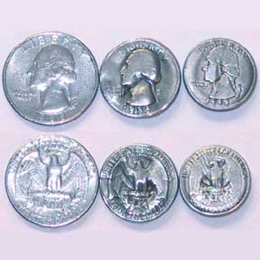
In the can cutter variation, an empty aluminum can is pinched in the center and shoots out both ends. In the coin shrinker version, a coin is placed inside a sacrificial coil and a blast shield is used. The coil blows apart into pieces of molten wire, leaving behind a shrunken quarter.
There are a couple ways to explain what happens. The first is to look at the eddy currents induced in the conductor, and then noting that the I x B forces are radially inward. Or, it can be treated as the force between antiparallel wires. Another way is to look at the magnetic energy which goes as B^2 and the magnetic pressure which is the gradient of B^2. The discharge happens on an RC timescale but the magnetic field penetrates the conductor in an L/R time. Before the field can penetrate there is a large gradient in the magnetic energy trapped between the conductor and the coil and this results in a radially inward force.
The current and instantaneous power in this device is enormous. The coin shrinking happens in about 40 microsec. The current is about 60,000 A and the power (during the discharge) is 360 MW, as much power as a small city uses for that instant.
Magnetic pinch technology is used for industrial metal forming. Thin tubes are crimped or welded and metal sheet can be magnetically pressed into a form.
The 4000 F capacitor above is charged to 120 V. If it is discharged by shorting the wires, a bang and flash results. But you can also connect it to a 20 watt light bulb, and the stored charge will light the bulb for several seconds.
A Leyden jar is a capacitor consisting of a glass can with aluminum foil inside and outside, which can be charged up to several tens of thousands of volts with an electrostatic generator. The jar will retain the charge for many minutes, showing charge storage by a capacitor. The jar can be discharged by bridging the inner and outer conductors with an insulated discharging wand and drawing a spark.
The Wimshurst generator [5] has Leyden jars that can be connected in or out of the circuit, illustrating several aspects of capacitors.
See also the Dissectible Leyden Jar [4].
A parallel plate capacitor has variable plate separation.
Some interesting demonstrations are:
a. The capacitor is connected to an electrostatic voltmeter. It is charged to one thousand volts with a high voltage supply. (The high voltage supply is in series with a lOOMohm resistor so its leads are safe to handle. The capacitor will be discharged in an instant if you put your fingers across the plates. Nothing will be felt; the stored charge Q with this capacitor is too small to make an appreciable current.) With the capacitor charged and disconnected from the power supply, the plate separation is now increased. Ask your students whether the voltage across the capacitor as shown by the electrostatic voltmeter will increase, decrease, or remain the same. Similarly, with the capacitor charged and disconnected from the power supply, a dielectric is thrust between the plates. Will the voltage increase, decrease, or remain the same?
 |
 |
b. A measuring amplifier can be inserted into the charging circuit from the high voltage power supply. Even after the capacitor is charged a slight leakage current will be noted. You can grasp the plates with your fingers, and the additional current flowing through your hand (protected by the l00Mohm resistor) will be noted on the meter. If the plate separation is increased, additional current will flow in to increase Q. A dielectric thrust in produces similar results.
 |
 |
In the "unitary imbecilometer" circuit the capacitor C charges slowly through the resistor R. When the voltage across C reaches the threshold of the neon light N (about 90 V), the capacitor discharges through the bulb, flashing it, and the cycle repeats. The frequency of flashes can be varied by varying R or C.
Zinc-copper-acid battery. Cut-away dry cell Batteries in series and parallel can be demonstrated.
Lemon cell - a copper and zinc nail pushed into a lemon will produce about 0.9 V on a meter. Two lemon cells hooked in series will light a small red led. Bring your own lemons.
Electrolysis of water apparatus is shown in the video below. NaOH is used as the electrolyte. The gasses are tested in the second video. Oxygen will relight a smoldering wood splint. Hydrogen causes a small pop when ignited.
The internal resistance of the Leybold multimeter on the 10 V scale can be measured with the circuit below:
The ammeter reads the entire current flowing through the internal resistance of the voltmeter, and the voltmeter reads the voltage drop across this resistance, so ri = V/i. You can check this by inserting a resistance decade box in series with the circuit and adjusting the resistance until the meter readings go to one half their former values. The decade box will then read the internal resistance of the voltmeter (assuming that of the ammeter is much smaller).
One way to measure the internal resistance of an ammeter is the circuit below.
The decade box R2 is set to zero, and R1 is chosen for an approximate full scale reading for the ammeter. R2 is then adjusted to halve this reading, so its resistance equals that of the ammeter.
ri for Leybold multimeter on 10 V scale = 34,000 ohms
ri for Leybold multimeter on 1 mA scale = 120 ohms
ri for Leybold projection meter on 1 mA scale = 100 ohms
A hot dog is impaled on nails connected directly to the 110 V AC line; alternatively DC can be used. Current passing through the hot dog will cook it in a minute or two. You can make the demonstration dramatic by putting the cooked hot dog on a bun with mustard or katsup, taking a bite, and handing it to the class to eat.
Bring your own hot dogs, buns, and mustard.
Kirchhoff's circuit laws and electrical power = Vi can be demonstrated with the light bulb board. The circuit is displayed to the class's view and voltages and currents can be measured in various places in the circuit.
A very interesting demonstration is to show a 100 watt bulb and a 60 watt bulb in parallel (as in an ordinary house circuit), and then to try the two bulbs in series (the 60 watt bulb is then brighter).
This board does not obey Ohm's law, however, since the resistance of the filaments depends on temperature, and therefore on voltage (or current). But you can demonstrate resistors in series and parallel by putting three 100 watt bulbs (or three 100 ohm resistors) in series and parallel and measure the resistance of the combinations with an ohmmeter.
A more compact version of the parallel and series light bulbs is available that uses a 12V car battery. All the light bulbs are 2.8W and can be hooked up in various configurations. The voltage and amps can be measured simultaneously using two digital multimeters.
You can wire up an ammeter or voltmeter by adding a shunt or series resistance to the Leybold 60 mV, 300 mA meter or other galvanometers. Alternatively, the Cenco multimeter has the shunt and series resistors ready to plug into a circuit that is fairly visible to the class.
You can wire up your own circuit with resistances and meters but two simple circuits using a large wirewound rheostat and demonstrating Ohm's law are a voltage divider and a current limiter.
The temperature coefficient of resistance can be investigated with a copper wire wound resistor and a carbon resistor. A small circuit with a battery, lightbulb and resistor is set up and then the resistor is put into a cup of liquid nitrogen. The change in light brightness indicates the sign of the temperature dependence. The temperature dependence of a semiconductor can be investigated by dipping a large green LED into liquid nitrogen and noting the color change.
Because any battery has an internal resistance ri its terminal voltage VT drops when current is drawn from it;
whereVo is the open circuit voltage. Measurements of VT for various i's are taken so ri can be determined. The circuit and operation are described over.
Students will be familiar with this effect from trying to start a automobile with the lights on. When the starter motor is actuated, the lights become noticably dimmer as the terminal voltage of the battery drops. A 12 V light bulb is provided in this circuit so the class can see it get dimmer as the large currents are drawn.
As of September 1979, the internal resistance of The J.C. Penney Battery was 0.02 ohms so it could deliver 600 A to a short circuit.
The circuit board for this demonstration allows the control and measurement of large currents (100 A) from a storage battery. The large currents are also used for magnetic fields of currents demonstrations.
High-Current Control Circuit
Basically the circuit routes the current from a 12 V storage battery through a series of 0.1W power resistors. When S2 is in the left position, the current passes through only one resistor, and will reach 120 A if there is no other resistance in the circuit. The single power resistor will heat up rapidly so this position must be used only momentarily. When S2 is in the right position, the current passes through the second power resistor. With S1 in the left position about 60 A will flow to a closed circuit; with S1 in the right position, the current flows through the third power resistor and 40 A flows.
The switch S3 is provided to short circuit the output for terminal voltage and internal resistance measurements.
The shunt w adjusts the Leybold 60 mV/300 mA meter to read 100A full scale at A, or 333 A full scale on its red scale when the series resistance r is switched in.
A voltmeter is hooked to V to read the terminal voltage of the battery.
Several multirange meters for measuring voltage and current in AC or DC are available including two large Leybold meters that can be used to monitor voltage and current in a circuit, and a large display digital multimeter that will measure voltage, current, resistance, and temperature.
Some professors have used the digital ohmmeter as a "lie-detector" -- a student volunteer was called up to answer embarrassing questions while holding the leads of the ohmmeter.
There are also large standing galvanometers, a model of a meter movement, and a measuring amplifier reading out onto a large meter for measuring small currents of 10-7 to 10-11 amps.
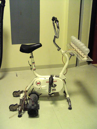
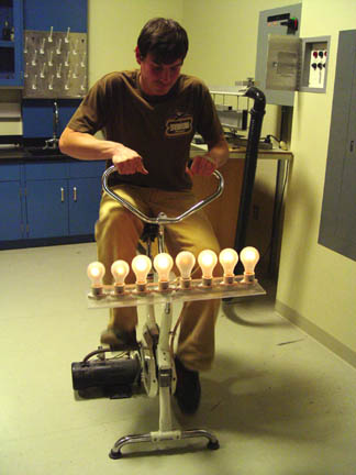
A person pushes the pedals of the the bicycle to generate enough current to light up to eight parallel light bulbs. The more bulbs the more resistance. Try it. you'll see.
Two solenoid coils connected by wires are arranged so that magnets on springs oscillate in them. When one magnet is set oscillating, the induced current causes the other to oscillate also.
In a variation of this demonstration known as Nefkens's Telephone the two coils are set on opposite sides of the lecture hall with a long wire connecting them. Just by arranging some pieces of iron and copper in the right way, movement here causes movement over there -- an astonishing achievement of the mind of Man.
Short the leads of one of the coils and the oscillation of the magnets will be rapidly damped out by Lenz's Law.
This apparatus is used in an 8E lab experiment. A spherical electron tube is mounted inside of a Helmholtz coil setup. The electrons are projected to circle in the magnetic field, and you measure the radius of the circle, the current to the Helmholtz coils, and the accelerating voltage to determine e/m. The electron path is made visible by dim ionization of the residual gas in the tube.
If the tube is twisted a little inside the coils, the circle becomes a helix. This is a very pretty demonstration of the path of charged particles in a magnetic field.
- The following experiments may fatally damage your microwave and will probably start a fire in your kitchen.
- A microwave oven can be used for various demonstrations including standing waves in an overmoded wave guide cavity, heating by electromagnetic waves, creation of plasma balls fed by microwaves, conduction of hot glass, superheating of fluids and others. A neon tube array shows the electric field pattern. Click on the picture of the array below to see a video of the array in the oven.
E-field in Microwave Oven
Lightbulbs in a Microwave Oven
Microwave Plasma Balls
A magnet thrust into a coil produces a noticable deviation on a table galvanometer. Or the coil can be moved over the magnet. (See also Special Relativity Demonstration [6])
In another demonstration two large coils are placed adjacent to each other, one connected to the galvanometer. When the other is pulsed with a battery, the induced current will be noted on the meter. You can emphasize the point that a steady current in the primary will induce no current in the secondary. If an iron core is positioned through the two coils, the galvanometer readings will become dramatically larger.
Faraday Bulb
A coil connected to a small bulb is mounted on a disk. When the disk spins the coil through the poles of a magnet, the bulb lights for that part of the arc for which the coil is passing through the magnet.
A small vacuum tube transmitter feeds an electric dipole antenna. The EM waves with l = 3m are picked up by a handheld dipole receiving antenna and detected by a peanut light bulb. Several aspects of dipole radiation can be illustrated with this setup:
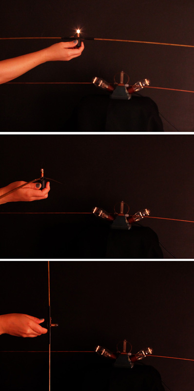
Modern Version of Hertz Wave Experiment
A VCR is set up with a videotape broadcasting on Ch 3. Instead of wiring the cable directly to the TV, it goes instead to a folded dipole antenna optimized for the frequency of Ch 3, which is 60 66 MHz. The receiver is a second folded dipole antenna which is connected to the TV (tuned to Ch 3), which acts as the detector.
It is easy to diplay the polarization of the EM waves by turning one of the dipole antennas at a right angle to the other. If there are standing waves in the room these can be seen by moving one antenna in relation to the other. From the distance between nodes the wavelength can be determined.
TV stations have a 6 MHz bandwidth. Channel 3 is 60 66 MHz which gives a wavelength of 5 meters. How are TV antenna oriented on a roof? That gives the polarization.
FM frequencies are 88 108 MHz
Broadcast antenna are horizontal or 45o
AM 550 1600 kHz
Vertically polarized antenna, usually center-fed dipole with image in ground.
Cellular phone antenna usually have a 10-60cm wavelength. From the antenna size you can guess the frequency.
The antenna used in this demo are folded dipole type made from 300 Ohm twin lead. They are connected to 75 Ohm cable through impedance transformers.
To see how the radio spectrum is divided up by users press here. [7]
A radio transmitting apparatus used by Marconi in 1895 in some of his earliest experiments.
You can show the rainbow spectrum of visible light with a dispersing prism [9] in front of a slide projector. A transparency of Maxwell's Rainbow, next page, is available.
An infrared detector connected to a meter visible to the class is placed beyond the red in the spectrum above. Why is the signal so small? Doesn't the tungsten lamp peak in the infrared? Ah, remove the "heat" absorbing glass element from the projector and the signal becomes large.
Ultraviolet light and the fact that it is absorbed by window glass can be demonstrated in connection with the photoelectric effect [10].
A radiometer consists of a spinner in a near vacuum with vanes silvered on one side and blackened on the other. When light, particularly infrared, falls on the radiometer, the black sides of the vanes become hotter and drive residual air molecules away from them, propelling the vanes around. (The rotation direction is contrary to that produced by radiation pressure, a smaller force.) A flashlight will operate the radiometer, but a match flame, which has more infrared, does much better. (Low powered lasers, of course, have too little energy to operate the radiometer.) Parabolic reflectors can be used to focus the infrared from a match or electric coil to spin the radiometer across the lecture hall.
Jumping Ring
A light aluminum ring, when placed on the iron core sticking out of a large AC electromagnet, is ejected violently into the air when the electro-magnet is activated. The conceptual explanation is that the AC magnet is continually reversing polarity, and induces a voltage in the ring so the ring's magnetic field continually opposes (repels) that of the iron core.
Copper rings and split rings are available to test also. A heavier copper ring will float midway up the iron core. When the ring is forced down on the iron core, it becomes very hot. A split ring will not move; it is not a complete circuit.
Magnetically Damped Pendulum
A pendulum with various disk is arranged to swing through the poles of a powerful permanent magnet. A solid aluminum disk is stopped on the first pass. An aluminum disk slotted to reduce eddy currents is moderately damped, and a cardboard disk swings freely.
Various rectangular plates can be released to fall through the poles of the magnet. An aluminum plate slides viscously, a slotted plate more rapidly, and a cardboard plate is unaffected.
Russian Version
Two rings are balanced on an arm which swings freely on a bearing. When a magnet is thrust into one ring, it is repelled away. (You can use this to illustrate the answer to the question in connection with the Faraday demonstration [11], "Where does the energy come from that moves the galvanometer needle?"). When the magnet is pulled out, the ring is attracted towards it. The other ring is split; thrusting a magnet in and out has no effect on it.
Osheroff Demonstration
A copper plate is cooled with liquid nitrogen to improve its conductivity. A falling magnet bounces without hitting the plate and lands on it's edge.
A large DC motor, with easily visible coils and split-ring commutator, operates from a 6 V battery. The motor can be rewired so that the field coils are energized. If the armature is now rotated by hand, a DC current is generated.
An AC-DC motor-generator has a single turn armature and both split and slip rings to act as a DC motor or an AC or DC motor or generator.
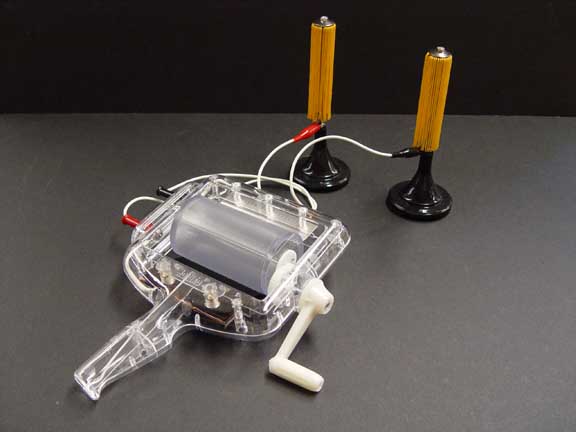
A hand-crank generator illuminates a neon bulb when cranked vigorously.
A small coil, mounted near the edge of a plexiglass disc, is connected to a peanut bulb. When the disc is spun between the poles of a powerful permanent magnet, the bulb is seen to be lit for that part of the circumference for which the coil passes through the poles of the electromagnet.
A tin can induction motor is demonstrated by holding a tin can on a special handle near two large coils at right angles. The coils are connected to the AC line, but one has a series capacitor to shift its phase 90° with respect to the other. This illustrates the starting circuit of the most common type of electric motor, the induction motor.
The hand-cranked generator is wired through a knife switch to an incandescent bulb. You can use a student volunteer to verify that it is much harder to crank the generator when the bulb is in the circuit, than when no current is being drawn. Ask your class why.
The Magnetic Levitator [12] has two coils at right angles connected to 120 VAC so the coils are 90° out of phase. These will rotate the suspended ball as in the tin can motor.
The secondary of a 1:1 transformer is hooked through a switch to a light bulb. The primary is hooked in series with another light bulb to the 120 V. line. When the switch is open neither bulb lights; the inductive reactance of the primary keeps the current small in the primary circuit. But when the switch is closed, both bulbs light! Now the secondary circuit is drawing current, so the mutual inductance of the two coils reduces the effective inductive reactance of the primary and enough current flows in the primary circuit to light its bulb.
Alternatively, conservation of energy tells us that the primary current must increase so that energy can be delivered to the secondary bulb through the magnetic fields linking the coils.
![]()
The Paul Trap, or rotating saddle trap, is an analogy to RF-electric quadrupole ion traping.
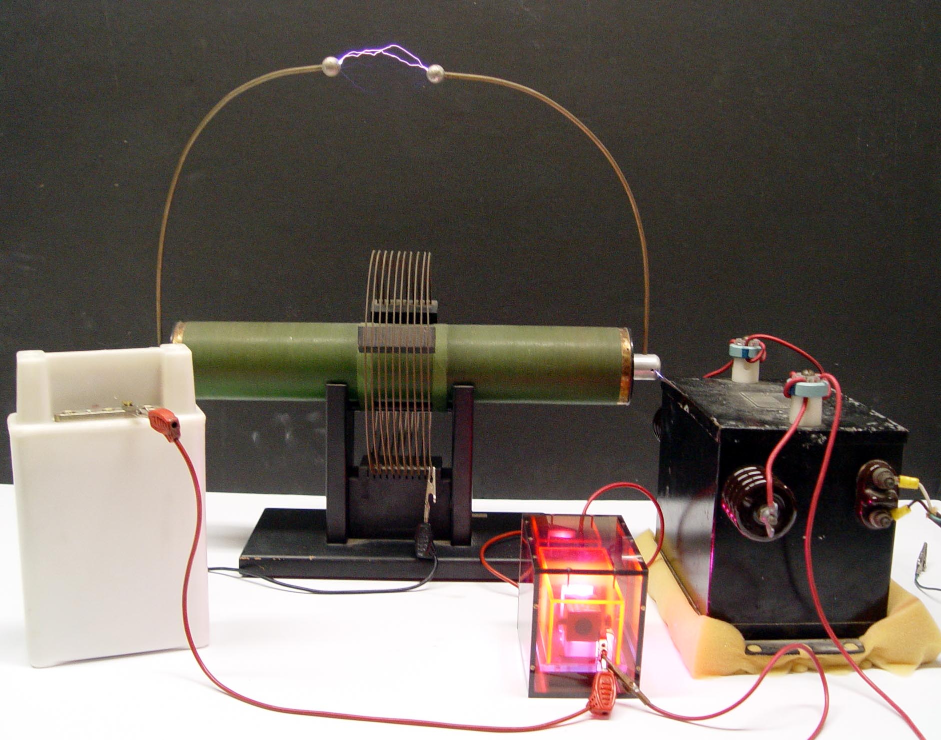
A Tesla coil is a high frequency, very high voltage transformer. The operation and circuit are described below. Our smaller Tesla coil radiates enough RF to illuminate a fluorescent tube a foot away. You can draw a one foot arc into your body, using a metal rod; the frequency is so high that the ions in your body do not have time to move far enough to do damage.
The Giant Tesla Coil generates a four foot discharge that will illuminate fluorescent tubes many feet away, and will generally terrify anyone anywhere near it. People with pace makers are supposed to move to the back of the room.
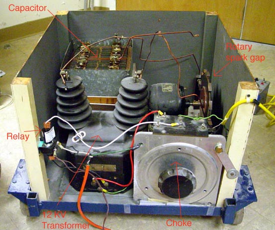
Tesla Circuit Operation
A preliminary step-up transformer boosts the line voltage to ten or twenty thousand volts. (A neon sign transformer is used for this purpose in the giant Tesla coil.) This voltage arcs across the spark gap F at 60 Hz, ringing the tuned circuit consisting of the capacitor C and the Tesla primary (a few turns) at 1-3 MHz. The Tesla secondary (many fine turns) has its own resonant frequency determined by its inductance and the internally distributed capacitance between its windings. The primary LC circuit is tuned to this resonant frequency for maximum coupling.
A spectacular demonstration with the small Tesla coil is to hold a fluorescent bulb in one hand and a metal rod in the other. When you draw an arc with the metal rod from the Tesla coil, the current passes through your body and lights the bulb. The voltage is over 1 million volts; why doesn't it shock or kill you? There are a number of hypotheses on this: a. The skin effect -- the current travels in the outer dead layer of skin. b. Human nerve circuits do not respond to high frequencies like 1 MHz, perhaps because of the reason mentioned above; there isn't time for the sodium and potassium ions to move far in the nerve cells. c. The impedance of the Tesla coil is very high, and it therefore induces only very small currents in humans.
A skin depth calculation using the conductivity of sea water, sigma = 4 mhos/m, gives a depth of 0.25cm, so this effect would not play a large role in protecting you, at least from pain stimulation on the skin surface. The answer is probably a combination of effects b and c from above. The current through the body is too small to generate enough heat to injure the person, and the high frequency does not stimulate pain nerves, or induce muscle contraction.
Our giant Tesla coil does sting you if you get into its circuit path to the ground. Tesla coil builders claim that the "gentleness" of the particular Tesla coil depends on the cleanness of the separation of 60 Hz and the high frequency at the spark gap.
A nice description of how the tesla coil circuit really works is here [13].
A demonstration transformer steps the 110 V AC line voltage up to 10,000 V for a Jacob's Ladder. The current arcs across the shortest distance between two upright conductors. Once started the arc rises, owing to the heated air, and jumps over a distance of several inches.
A secondary of few turns can be substituted to make a stepdown transformer. The low voltage - high current can be used to spot weld sheet metal or to melt a tin ring.
Transmission Line
![]()
A signal generator capable of 10 MHz is hooked to a T-connector at channel 2 of an oscilloscope through an 8 meter 50 ohm cable as shown above. Channel 1 of the scope is hooked to the same source through a short cable.
Input a pulse at 1 MHz; sweep at 0.5 ms/cm
Input a sine wave
Suggested by Brad Tippens
In the ideal case the magnetic field lines of a toroidal coil are entirely contained witnin tne coil and = 0 outside. This can be checked by using a flip-coil, Hall probe, or compass needle near the toroidal coil.
However, the lines of vector potential circle the flux lines:
So A is not zero outside the coil.
If a wire is threaded through the hole of the toroid and returned through the hole, case 1, no galvanometer deflection is seen as B is switched on and off. But if the wire is threaded through the hole and returned around the coil, case 2, a galvanometer deflection will be seen from = -d/dt.
Protoboards, 15V and other power supplies, meters, components, etc. are available for hooking up your own electronic circuits.
A small solar cell when placed under a flood light runs a propeller.
The intrepid researchers in the demolab have discovered the secret of Blue Love. It's electricity. One side charges up positive, and one side negative. See for yourself.
The apparatus is shown below.
This is a very nice demonstration of Coulomb's Law with a fancy torsion balance and Laser spot readout. You can show that the electrostatic force varies as the square of the distance and is proportional to one of the charges. It is probably a good idea to practice a little with this one before hand.
This is a very impressive demonstration which will draw lots of comment! It can be used to emphasize the difference between conductors and insulators.
The dissectable Leyden jar is charged up with a Van de Graaff and then discharged by shorting the inner and outer can to show charge storage. Then the jar is recharged and disconnected from the Van de Graaff. The inner can is lifted out with an insulated tool, or, with care, by hand. At this point the parts of the jar are safe to handle, and the glass jar can be lifted out, the inner and outer cans touched to each other, or touched to the glass jar in any combination. You can even give the pieces to the students to handle.
When the Leyden jar is reassembled, the last step of inserting the inner can being done carefully, it will be found that the jar is still charged, as can be checked by shorting its terminals and drawing a spark.
 |
 |
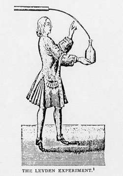 The discovery of the Leyden jar as described in a letter written by Musschenbroeck to Reaumur in 1746.
"I wish to inform you of a new, but terrible experiment, which I advise you on no account personally to attempt. I am engaged in a research to determine the strength of electricity. With this object I had suspended by two blue silk threads, a gun barrel, which received electricity by communication from a glass globe which was turned rapidly on its axis by one operator, while another pressed his hands against it. From the opposite end of the gun barrel hung a brass wire, the end of which entered a glass jar, which was partly full of water. This jar I held in my right hand, while with my left I attempted to draw sparks from the gun barrel. Suddenly I received in my right hand a shock of such violence that my whole body was shaken as by a lightning stroke. The vessel, although of glass, was not broken, nor was the hand displaced by commotion: but the arm and body were affected in a manner more terrible than I can express. In a word, I believed that I was done for."
An E-field projection device with self-contained fluid is available. You can change the electrodes and show several different field patterns such as +/- point charges, parallel plates and others in a few minutes. This device is charged by a piezoelectric gun, not the Van de Graaff as shown in the animation below.
The equipotentials of a charged sphere are concentric spheres centered on the charged sphere. A small fluorescent tube is held on a plastic meter stick near the charged Van der Graaff sphere. When the tube is along a radial line of the sphere, the tube lights; the ends are at different potentials. But when the fluorescent tube is held tangent to a concentric sphere, the tube does not light; the ends are at the same potential.
To show that work is done in bringing a charge up close to another charge, alternately touch the grounded discharge rod to the Van der Graaff sphere and move it away. When the sphere is grounded the motor driving the belt runs faster - -more freely. No work is done to bring charge up. But when the grounding rod is moved away, the motor slows down, "lugging" away to carry charge up the belt close to the charge building up on the sphere. The charge carried up on the belt is delivered to the center of the sphere, whence it quickly moves to the outside of the sphere in obedience to Gauss's Law. As the charge on the sphere builds up, it begins to leak into the air. Equilibrium is reached when the charge leaks off the sphere as fast as the belt is able to bring new charge up.
An electrophorus consists of a flat insulator on which rests a removeable metal plate. The Lucite base of the electrophorus is charged positive by rubbing it with silk. When the metal plate is placed on it, the metal contacts the lucite in only a few spots and acquires very little positive charge. But if the metal plate is now grounded (by touching it with your finger), it acquires a large negative charge by induction.
The metal plate is now lifted off and its negative charge can be detected at some distance with an electroscope or with pith balls. The charged plate will cause a half-inch spark to jump to your knuckles (painless), or it will flash a neon or fluorescent tube briefly (best seen by turning off all lights).
The operation of charging the metal plate by induction can be repeated indefinitely, since essentially no positive charge is removed from the insulator base. You may wish to ask your class where the energy comes from, which could be used to flash a fluorescent tube indefinitely.
This demonstration uses a Van der Graaff generator, a 10 cm test sphere on an insulating handle, a can mounted on an electroscope (the "ice pail"), and a second electroscope to test for charge. The "medium" difficulty of the demonstration is in remembering to do all the steps in the correct order.
Version 1: The induced charge equals the inducing charge

Charge the small sphere with the Van der Graaff. Ground the Van der Graaff sphere and the pail to make sure there is no extra charge around. Show that the small sphere is still charged by bringing it near the second electroscope.
Lower the small sphere into the pail without touching it. The electroscope deflects. Remove the sphere, and the deflection disappears.
Lower the sphere into the pail again without touching it. The electroscope deflects. Ground the pail by touching it. The deflection disappears. Remove the sphere. The electroscope deflects again. You have induced a charge, opposite in sign to that on the sphere, onto the pail from the ground. We will now prove that the magnitude of this induced charge on the pail is equal to the magnitude of the charge on the sphere.
Lower the sphere slowly into the pail. The deflection goes to zero. Lower the sphere down until it touches the bottom of the pail. If you listen carefully, you can hear the sound of the spark jumping. The deflection remains zero. Now take the sphere out. The deflection remains zero, and you can test the there is no charge on the sphere by bring it to the second electroscope. All charge has been neutralized.
Suggested by Bill Layton
Version 2: Gauss's Law
Start as above. Charge the small sphere and lower it into the pail without touching it. The electroscope deflects. Remove sphere. Deflection disappears. Put sphere back in. Deflection returns. Lower the sphere so it touches the bottom of the pail, and you can hear a spark jump. Deflection remains unchanged. Remove the sphere. Deflection remains unchanged. Finally, bring the sphere to the second electroscope. There is no deflection. The sphere is completely discharged. All of the original charge on the sphere went over to the pail.
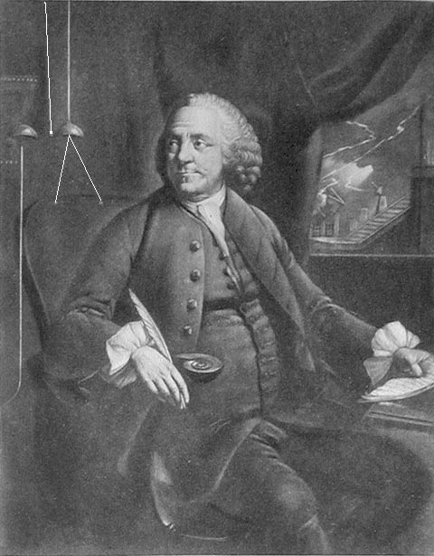
When a charged cloud went overhead the bells rang to alert Franklin so that he could do his experiments. A pair of pith balls allowed him to determine which charge (positive or negative) the cloud carried. We have a set of Franklin's bells that can be charged with the Van De Graaff Generator.
That charge is only on the outside surface of a conductor is shown by several demonstrations.
| a. A hollow cylinder is connected to a Van De Graaff generator. Pith balls hanging on the outside fly up wildly but pith balls hanging from the inside barely stir. |
|
|
b. Faraday Cage - -When a Van de Graaff is turned on, it will affect an electroscope at a distance of a meter or more. However, when a metal cage is put over the electroscope, the electroscope is not affected, even if the apparatus is moved close enough so sparks jump to the cage. |
|
 |
 |
| c. Faraday Pail - -a small metal can is placed on the electroscope. A "charge carrier" (a small metal ball on an insulated rod) is used to transfer charge from an electrophorus plate or Van de Graaff sphere to the inside of the can. Since this charge immediately flows to the outside of the can, several more "spoonfuls" of charge can be added to the can in this manner, as shown by the increasing deviation of the electroscope leaves or needle. This, then, is the principle of the Van de Graaff generator - - charge is continually carried up by the belt to the center of the sphere, whence it accumulates on the outside. |
|
 |
d. A very definitive demonstration of Gauss's Law is provided by a large hollow sphere with an opening in the side and an electrode in the center. The hollow sphere is charged by connecting a conducting rod from the center electrode to a Van de Graaff generator. Charge can now be removed from the outside of the hollow sphere by touching it with a charge carrier. The charge carrier is touched to an electroscope to show the presence of charge. But if the charge carrier is touched to the center electrode of the charged hollow sphere, no charge can be removed. All the charge has flowed to the outside of the sphere. (The insulated metal ball of the charge carrier should be touched very gently to the electroscope; otherwise, the indicating needle will be banged up, confusing the students.) |
Cold, dry days are best for these demos.
| a. A rubber rod is charged negative by rubbing it with rabbit's fur. A lucite rod is charged positive by rubbing it with silk. When one charged rubber rod is placed in a stirrup, another charged rubber rod will repel it, but a charged Lucite rod will attract it. This simple but graphic demonstration shows that charges come in two sorts. | |
 |
 |
 |
b. The charged rods will pick up bits of paper and styrofoam by polarization. |
| c. The charged rods will first attract hanging pith balls by polarization. When the balls touch the rod, they acquire some of its charge and thereafter are repelled from the rod strongly. The pith balls now hang apart, repelling each other. |  |
 |
d. If a charged rod is brought near an electroscope, its leaves will diverge. If the rod is touched to the electroscope, the leaves will remain diverged, even when the rod is moved away. The electroscope can be charged by induction by grounding it with your finger when the charged rod is near. Remove your finger and then the rod, and the electroscope is now charged with the opposite charge of the rod. This can be checked by bringing the charged rod near again; the leaves now come together. |
 |
 |
Note: All electrostatic demos work better on cold, dry days.
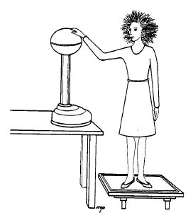
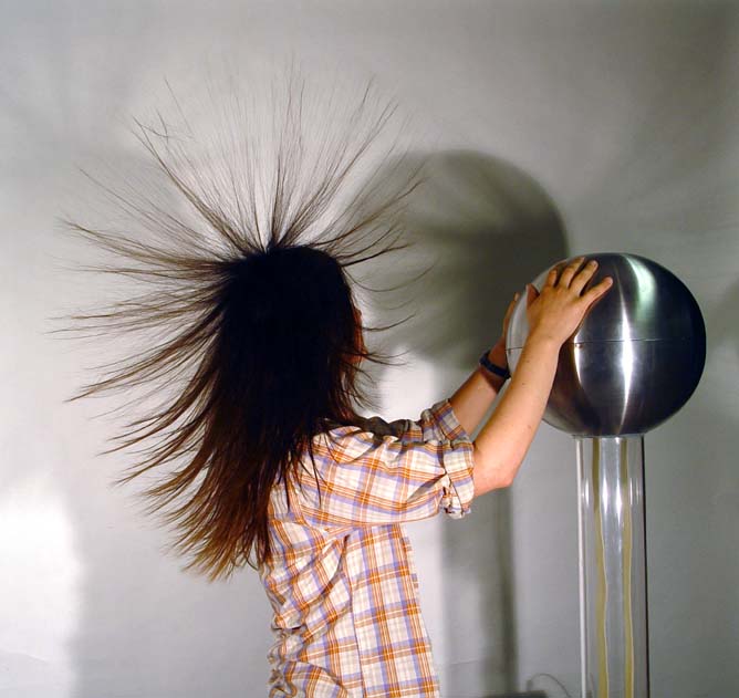
| a. Charge flows to the points and sprays off. In this classic demonstration, the professor or a student volunteer stands on the insulated base and places his/her hand on the sphere of the generator. An assistant turns the generator on, and the demonstrator's hair stands on end. The demonstrator should have a key or other pointed object concealed on his person to hold up and spray off the excess charge when the demonstration is over.
A similar effect can by demonstrated by placing a wig on the sphere, or by connecting the sphere to a paper plume. The electric flier shown below will spin by spraying off charge when connected to the sphere. |
|
 |
 |
| b. Action of a lightning rod. Two Van de Graaffs are provided, one of which charges its sphere positive, and the other negative. When both are turned on, they will spark to each other over 8 -12" distance. However, if a small point is placed on one sphere, aimed in any direction, even at the other sphere, no sparks will jump, because the point dissipates the charge into the air preventing the potential from building up. | |
 |
 |
| c. Charge density is Greatest at the areas of highest curvature. When the pear-shaped metal sphere is charged by touching it to the Van de Graaff, a larger charge can be removed from the narrow end than from the fat end. The amount of charge is tested by the deflection of an electroscope. To produce a noticeable effect this demonstration must be done carefully. |  |
 |
d. Gauss' Law --charge is on the outside of a conductor. Several demonstrations of these effects are described here [14]. |
| e. Conductors and non-conductors. A string connected between an electrostatic generator and an electroscope will not conduct charge, but a metal wire will. | |
 |
 |
| f. Smoke precipitator. Smoke blown into a tube (from a cigarette) rapidly disappears when the electrodes on the ends of the tube are connected to the generator. |  |
|
|
g. "Shot from guns" A paper cup full of puffed wheat or small Styrofoam chips placed on top of the generator produces a spectacular effect. Bring your own puffed wheat. |
The Wimshurst Static Machine generates large sparks for entertainment or for use in various electrostatic experiments. The associated Leyden jars can be connected in or out of the circuit to illustrate the function of a capacitor -- in circuit, the sparks are much fatter and louder (Q larger), but of the same length (same maximum V), and much less frequent (longer time to build up the large Q).
 |
 |
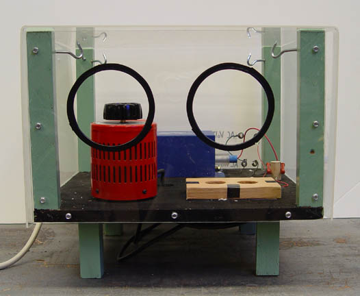
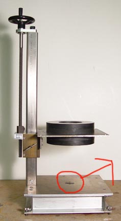
In 1994 Andrew Alcon patented* a simple device which stably levitates a magnet above two counter-rotating aluminum rotors.
The motors used in this demo are 5,000 RPM, 1/15 HP, 115 VAC Dayton model 2M066. The aluminum rotors are carefully made to spin true. A light dimmer circuit is used to control the speed of the motors.
*US Patent 5,319,336
The small floating magnet is balanced against gravity by the upper ring magnet. This levitation configuration is unstable vertically, but stability is provided by the diamagnetic carbon plates above and below the floating magnet. The diamagnetic material produces repelling forces as the floater approaches, pushing it back to its center position and overcoming the vertical instability.
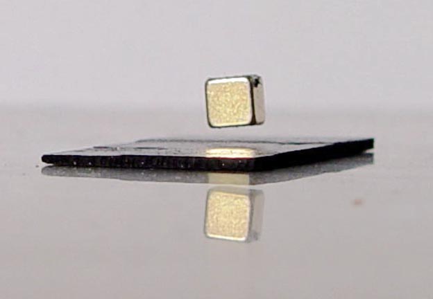
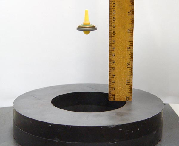
A small sample of a type I superconductor will demonstrate the Meissner Effect (levitating a magnet) when cooled in liquid nitrogen.
Another example of superconductivity can be demonstrated using a type II superconductor.
A piece of superconducting material is cooled with liquid nitrogen on top of a track array of magnets. When the superconductor cools, it floats atop the magnetic array. If the track is turned upside down, the superconductor goes from being levitated to suspended due to flux pinning which freezes the magnetic flux within the type II superconductor.
Video of diamagnetic levitators showing many objects including hazelnuts, strawberries, and a living frog.
An electromagnet suspends an iron ball in mid air. An IR LED and phototransistor pickup senses the position of the ball, and the associated electronic circuitry controls the current to the magnet by active feedback. Two other magnets 90° apart and 90° out of phase can cause the suspended ball to spin.
A wire in the form of a trapeze swing hangs between the poles of a powerful magnet. When a current is passed through the wire, it jumps violently out from the poles.
A power resistor set-up is used with a storage battery to deliver a hundred amperes to a heavy copper wire to orient iron filings or compass needles for overhead projection.
This demonstration is an excellent illustration of tne vector cross product. A beam of electrons is outlined on a fluorescent card in the tube. A magnet brought near the beam neither attracts it or repels it, but bends it "sideways" according to the F = qv x B law.
 |
 |
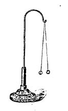
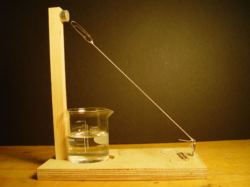
A magnet deflects the large curly filament of a light bulb connected to a DC source. If an AC source is used, the filament vibrates impressively (See AC-DC Difference [16]).
A model of a meter movement shows how a coil rotates in the field of a permanent magnet when a current is pulsed through it.
Often during his lectures at the University of Copenhagen H. C. Oersted had demonstrated the non-existence of a connection between electricity and magnetism. He would place a compass needle near to and at right angles to a current carrying wire to show that there was no effect of one on the other. After one of the lectures a student asked, "but, Professor Oersted, what would happen if the compass needle was placed parallel to the current carrying wire?" Oersted said, "Well, let's see," and went down in the history of physics; the student's name is forgotten.
(Adapted from H.E. White, Modern College Physics, pp 433, D. Van Nostrand, Princeton, 1962)
Large currents passed through two neighboring parallel wires cause them to attract dramatically, or to repel if the currents are passed antiparallel.
A box with parallel and antiparallel wires made of aluminum foil exists for lecture demonstrations. The box sits on the overhead projector and is powered with a 12V supply. The motion of the wires is easily detected by the class as the experiment is magnified on a screen.
A long straight wire demonstration, a solenoid field, and a field of a current loop are available in compass table form. Many tiny compass needles turn to outline the magnetic fields for overhead projection, saving you the trouble of carefully spreading the iron filings.
A similar arrangement for overhead projection shows the magnetic field of a loosely wound solenoid coil.
 |
 |
Domains are well modeled by the compass table, an array of about one hundred small compass needles used for showing fields of bar magnets, etc. When there is no strong external B-field, sections of the array line up in different directions, each individual compass needle aligning itself with the local field. When the array is tapped sharply, it will be seen that the needles on the boundaries of the domains are the least stable (vibrate the most), and some of them realign causing one domain to grow at the expense of another.
In the Barkhausen effect, a large coil of fine wire is connected through an amplifier to a speaker. When an iron rod is placed within the coil and stroked with a magnet, an audible roaring sound will be produced from the sudden realignments of the magnetic domains within the rod. A copper rod, on the other hand, produces no effect.
This pretty demo uses a "permalloy" rod, a soft iron rod, a hammer, and the compass dip needle (which is shown here [17]).
|
|
Using the dip needle find the direction of the earth's magnetic field in the class room (plunging about 60° earthward to the magnetic north). Arrange the soft iron rod perpendicular to the earth's field, and strike its end several times with a hammer. This insures that it is demagnetized, which is demonstrated by showing that either end of the rod will attract either end of the compass needle (by magnetic polarization). Now align the rod with the earth's field and strike it several times to shake its domains around and magnetize it. That the rod is magnetized is demonstrated by showing that the north end of the rod repels the north end of the compass needle and the south end of the rod repels the south end of the compass needle. This rod retains its magnetization, no matter how it is oriented in the earth's field.
However, the permalloy rod is so compliant that if held along the earth's field its north end will repel the north end of the compass needle, and now if it is smoothly reversed without any hammer strikes, the other end will repel the north end of the compass needle! Its domains line up with the earth's field without any impact blows.
A small wheel has monel metal wrapped around its circumference. A small light bulb is positioned to heat one part of the circumference, raising the metal above its Curie temperature so it no longer responds to magnetism. When the wheel is placed in the field of a strong magnet, it rotates slowly as one part of the circumference is continually rendered non-magnetic by the heat of the light bulb.
A nickel paper clip (a regular steel one is available too) attached to a base with a string is suspended in air by the use of a magnet. If the nickel paper clip is heated with a lighter (for the steel paper clip a blowtorch is required) beyond a certain temperature called the Curie temperatures it is no longer attracted by the magnet.
The Curie temperature (Tc) is the critical temperature beyond which a previously ferromagnetic material becomes paramagnetic. On the atomic level, below the Curie temperature the magnetic moments, contributed mainly by the electrons, are aligned in their respective domains and even a weak external field results in a net magnetization. As the temperature increases to Tc and above however, fluctuations due to the increase in thermal energy destroy that alignment. Tc for nickel is 631K, while that for iron is 1043K.
A magnetic declination and inclination needle is provided for determining the direction (deviation and dip angle) of the earth's magnetic field in the classroom.
A globe of the earth may help to illustrate these concepts.
The total magnitude of the magnetic field vector is about 0.5 Gauss units or equivalently 50,000 nanoTeslas (nT). To find the components of the magnetic field anywhere visit the Standard magnetic Field Model [18] and enter the date, and your geographic latitude, longitude and elevation. The table below shows the representative components for June 1, 1999 at sea level. Bx, By and Bz are the components in units of nT, B is the total field strength also in units of nT, D is the declination angle between geographic and magnetic north, and I is the inclination or Dip Angle, in degrees below the local horizontal plane.
Average Magnetic Components
| City | Bx | By | Bz | B | D | I |
| Los Angeles | 24276 | 5996 | 41636 | 48568 | 13.9 | 59.0 |
| New York | 19308 | -4643 | 50289 | 54068 | -13.5 | 68.5 |
| Boston | 18006 | -1566 | 53490 | 56461 | -4.9 | 71.3 |
| Chicago | 18686 | -803 | 52908 | 56117 | -2.5 | 70.5 |
| Miami | 25478 | -2182 | 38586 | 46290 | -4.9 | |
| Huston | 24892 | 2050 | 42441 | 49245 | 4.7 | 59.5 |
| Denver | 20895 | 3878 | 49938 | 54272 | 10.5 | 66.9 |
| San Francisco | 23004 | 6411 | 43851 | 49932 | 15.5 | 61.4 |
There are 3 ball bearings stuck to a magnet in a track. A fourth ball bearing is released on the opposite side of the magnet, and is attracted to it. The ball at the other end shoots off at a much higher velocity. Where does the energy come from?
A second version of the gauss cannon is below and uses one spherical magnet which looks identical to the ball bearings. The device can first be shown without the magnet, when it acts like Newton's cradle and conserves energy. With the magnet, the end ball shoots off the end of the ramp.
The circuit below, from Physics Demonstration Experiments Volume 2 by Harry Meiners, page 972, will draw a hysteresis curve on the oscilloscope. The twenty ohm resistor serves to measure the current to the transformer primary producing a horizontal signal proportional to H. The output of the secondary of the transformer is proportional to dB/dt. The final RC circuit integrates this (see RC Integration and Differentiation [19]) to produce a vertical signal proportional to B. As you adjust the variac to control the current to the primary, the curve on the oscilloscope stretches out to saturation.

A compass table with a hundred or so tiny compass needles displays the magnetic field of a bar magnet, or two attracting or repeling magnets, for overhead projection. The compass table replaces the old iron filing magnetic field demonstrations (which are still available).
 |
 |
Compass tables are also used to show the magnetic fields of a long straight wire, a solenoid coil, and a current loop (see Solenoid and Loop Fields [20] and Parallel Wires [21]). The "magniprobe" is a tiny bar magnet completely free to rotate on gimbals in any direction. It will display the three dimensional form of the magnetic field of a bar magnet, delighting the instructor. However, the device is too small to be seen by more than a few students at once unless enlarged on TV. The "Mark II" version of the magniprobe is sensitive enough to detect the earth's field.
| Various magnets and compasses are available; the strongest magnets are the little ceramic magnets, these can be handed around to the class. |
|
| A piece of lodestone picks up small iron objects, or can be suspended so as to point north. | |
 |
 |
| A large, strong bar magnet repels another held by braces and suspends it several inches in the air. |
|
| Using the dip needle find the direction of the earth's magnetic field in the class room (plunging about 60° earthward to the magnetic north). Arrange the soft iron rod perpendicular to the earth's field, and strike its end several times with a hammer. This insures that it is demagnetized, which is demonstrated by showing that either end of the rod will attract either end of the compass needle (by magnetic polarization). Now align the rod with the earth's field and strike it several times to shake its domains around and magnetize it. That the rod is magnetized is demonstrated by showing that the north end of the rod repels the north end of the compass needle and the south end of the rod attracts it. | |
 |
|
| A small electromagnet operated from a battery will pick up nails, etc. |
|
|
|
A giant compass needle is useful for demonstrating the earth's magnetic field and for determining the north and south poles of various magnets. |
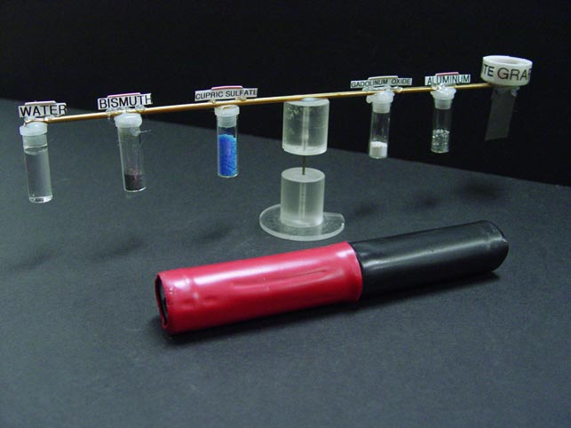
A torsional balance contains various vials of paramagnetic and diamagnetic material including graphite and gadoliminium oxide.
![]()
Diamagnetic graphite can be used to stabilize magnetic levitation.
![]()
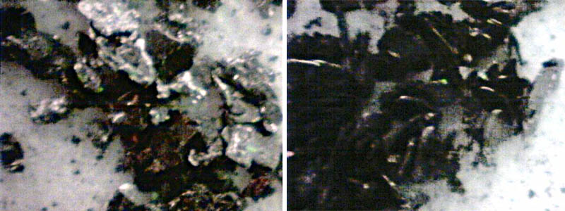
Microscopic graphite dust is made of flakes which lie flat and reflect a silver light (left view). When put over a magnetic field, the flakes stand up on edge due to graphite's diamagnetic property (right view). Only the top edges reflect light, and the powder looks very black. Light goes in, scatters into the deep valleys, and never comes out. The blackest black has been produced using a forest of aligned carbon nanotubes.
Rowland's Ring is used to demonstrate the magnetization curve of iron. (See Halliday and Resnick, Part II, Sec. 37.6) We have an actual Ring, or the Leybold demountable transformer will serve.
The flux in the iron is measured by switching off the current in the energizing coil and recording the reading of a ballistic galvanometer hooked to a pickup coil. (You can show that the maximum reading of a ballistic gavanometer is proportional to q = i t, which is in turn proportional to the change in flux through the pickup coil. You can determine the constant of proportionality by discharging a known capacitor through the galvanometers.) The large demonstration galvanometer will serve as a ballistic galvanometer for lecture purposes.
Professor J. Oostens has suggested the following demonstration of magnetic saturation and reluctance:
The Leybold transformer is arranged as above. The experiment is run first with no gap for several values of the current. Then a small gap is provided with shims, and the measurements repeated for the same set of currents. A Hall probe and Gaussmeter can be introduced in the second case for more accurate measurements of B in the gap. Sample data are shown below:
| I
(amps) |
nI
(amp.turns) |
GFe
(units) |
GGap
(units) |
BCap
(Tesla) |
<--higher degree of accuracy. |
| 10 | 2500 | 1.2 | 1.3 | 0.89 |
Some deviation is due to a remiant field. (Iron behaves like a magnet for very low currents) |
| 5 | 1250 | 1.1 | 0.75 | 0.50 | |
| 3 | 750 | 0.95 | 0.45 | 0.28 | |
| 2 | 500 | 0.8 | 0.27 | 0.19 | |
| 1 | 250 | 0.7 | 0.1 | 0.090 | |
| 0.5 | 125 | 0.45 | 0.05 | 0.012 |
The graph shows that the field in the iron quickly reaches saturation. By computing the reluctance,
Reluctance = magnetomotive force / flux = nI / Φ
you can show that the reluctance of the air gap is much greater than that of the iron, even though the path length is much smaller.
An undamped compass needle vibrates about equilibrium in a B-field; the vibration frequency can be used as a measure of B. Let the (unknown) moment of inertia of the compass needle be I, and its (unknown) magnetic moment μ. Then the restoring torque τ=Bμsinθ. Using the analogy to linear harmonic motion the angular frequency of vibration is
ω = √ (k/m) = √ (Bμ/I)
Thus, the frequency of vibration of the needle is proportional to √B. Measure the frequency of vibration of the compass needle in the Earth's field of 0.5 gauss, and obtain the strength of other B-fields from these results.
Gauss Meter
Accurate and detailed measurements of B-field can be made with a Gaussmeter and Hall probe. You can illustrate the size of the gauss unit and the strength of various magnets, or make measurements of B-fields for electron deflection, etc.
Links:
[1] https://demoweb.physics.ucla.edu/node/167
[2] https://demoweb.physics.ucla.edu/node/169
[3] https://demoweb.physics.ucla.edu/node/185
[4] https://demoweb.physics.ucla.edu/node/179
[5] https://demoweb.physics.ucla.edu/node/182
[6] https://demoweb.physics.ucla.edu/node/199
[7] http://www.ntia.doc.gov/osmhome/allochrt.pdf
[8] https://demoweb.physics.ucla.edu/sites/default/files/HertzWavesm.jpg
[9] https://demoweb.physics.ucla.edu/node/208
[10] https://demoweb.physics.ucla.edu/node/209
[11] https://demoweb.physics.ucla.edu/node/197
[12] https://demoweb.physics.ucla.edu/node/205
[13] http://www.richieburnett.co.uk/operation.html
[14] https://demoweb.physics.ucla.edu/node/219
[15] http://www.physics.ucla.edu/marty/levitron/
[16] https://demoweb.physics.ucla.edu/node/165
[17] https://demoweb.physics.ucla.edu/node/249
[18] http://www.ngdc.noaa.gov/seg/geomag/magfield.shtml
[19] https://demoweb.physics.ucla.edu/node/174
[20] https://demoweb.physics.ucla.edu/node/238
[21] https://demoweb.physics.ucla.edu/node/239