
The voltage in the circuit above is adjusted so that the light bulb glows dimly. When the switch is opened, the bulb will flash much brighter momentarily as the magnetic field collapses around the inductor.
A neon bulb can be substituted and the voltage adjusted far below threshhold. The neon bulb will flash when the switch is opened, showing that the back EMF is much larger than the steady voltage.
The circuit can be arranged to produce a large spark when the switch is opened.
Impressive sparks are produced when various capacitors are discharged.
A 4000 F capacitor is charged to 150 V. It can then be carried close to the class and snapped in front of them. This is guaranteed to wake up the sleepers!
A Leyden jar is charged to 50,000 V with a Van de Graaff generator. It can even be disassembled and the outer and inner cans touched together, and then reassembled (carefully! ). Now, when the outer and inner cans are bridged by a discharge wand, a half-inch spark jumps. (See E.1.5 [1]).
 |
 |
Wire exploder: A 175 F capacitor is charged to 4000 V and discharged through a small wire. The wire vaporizes with a large bang and flash. This demonstration is dangerous and must be performed by a lecture demonstration staff member.
Sources of 110 V AC and DC are fed alternately to a standard incandescent bulb in series with a large inductance or capacitance. The capacitance will "pass"AC but "block" DC, whereas the inductance will "block" AC and "pass" DC. With the AC supply, if an iron core is lowered into the inductor coil, increasing its inductance, the light bulb becomes dramatically dimmer, illustrating a theater light dimmer circuit.
 |
 |
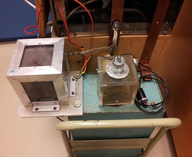
This apparatus is based on a fusion energy device called a theta pinch. A large capacitor is charged and a high current switch discharges it through a coil with just a few turns. The "theta" current in the coil produces a radial pinching effect on any conductor inside the coil.
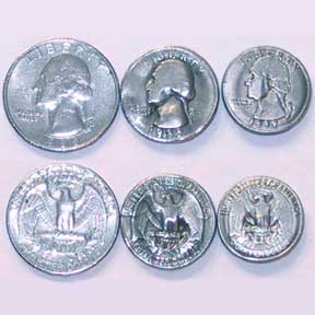
In the can cutter variation, an empty aluminum can is pinched in the center and shoots out both ends. In the coin shrinker version, a coin is placed inside a sacrificial coil and a blast shield is used. The coil blows apart into pieces of molten wire, leaving behind a shrunken quarter.
There are a couple ways to explain what happens. The first is to look at the eddy currents induced in the conductor, and then noting that the I x B forces are radially inward. Or, it can be treated as the force between antiparallel wires. Another way is to look at the magnetic energy which goes as B^2 and the magnetic pressure which is the gradient of B^2. The discharge happens on an RC timescale but the magnetic field penetrates the conductor in an L/R time. Before the field can penetrate there is a large gradient in the magnetic energy trapped between the conductor and the coil and this results in a radially inward force.
The current and instantaneous power in this device is enormous. The coin shrinking happens in about 40 microsec. The current is about 60,000 A and the power (during the discharge) is 360 MW, as much power as a small city uses for that instant.
Magnetic pinch technology is used for industrial metal forming. Thin tubes are crimped or welded and metal sheet can be magnetically pressed into a form.
The 4000 F capacitor above is charged to 120 V. If it is discharged by shorting the wires, a bang and flash results. But you can also connect it to a 20 watt light bulb, and the stored charge will light the bulb for several seconds.
A Leyden jar is a capacitor consisting of a glass can with aluminum foil inside and outside, which can be charged up to several tens of thousands of volts with an electrostatic generator. The jar will retain the charge for many minutes, showing charge storage by a capacitor. The jar can be discharged by bridging the inner and outer conductors with an insulated discharging wand and drawing a spark.
The Wimshurst generator [2] has Leyden jars that can be connected in or out of the circuit, illustrating several aspects of capacitors.
See also the Dissectible Leyden Jar [1].
A parallel plate capacitor has variable plate separation.
Some interesting demonstrations are:
a. The capacitor is connected to an electrostatic voltmeter. It is charged to one thousand volts with a high voltage supply. (The high voltage supply is in series with a lOOMohm resistor so its leads are safe to handle. The capacitor will be discharged in an instant if you put your fingers across the plates. Nothing will be felt; the stored charge Q with this capacitor is too small to make an appreciable current.) With the capacitor charged and disconnected from the power supply, the plate separation is now increased. Ask your students whether the voltage across the capacitor as shown by the electrostatic voltmeter will increase, decrease, or remain the same. Similarly, with the capacitor charged and disconnected from the power supply, a dielectric is thrust between the plates. Will the voltage increase, decrease, or remain the same?
 |
 |
b. A measuring amplifier can be inserted into the charging circuit from the high voltage power supply. Even after the capacitor is charged a slight leakage current will be noted. You can grasp the plates with your fingers, and the additional current flowing through your hand (protected by the l00Mohm resistor) will be noted on the meter. If the plate separation is increased, additional current will flow in to increase Q. A dielectric thrust in produces similar results.
 |
 |
In the "unitary imbecilometer" circuit the capacitor C charges slowly through the resistor R. When the voltage across C reaches the threshold of the neon light N (about 90 V), the capacitor discharges through the bulb, flashing it, and the cycle repeats. The frequency of flashes can be varied by varying R or C.
Links:
[1] https://demoweb.physics.ucla.edu/node/179
[2] https://demoweb.physics.ucla.edu/node/182