- 1. Mechanics
- 2. Harmonic Motion, Waves and Sound
- 3. Matter and Thermodynamics
- 4. Electricity and Magnetism
- 5. Light and Optics
- 6. Modern Physics
- 7. Astronomy
- 8. Software and Multimedia
- 9. Index and code conversion from older manual
- External Resources
80. The 90D Phase Shift of a Capacitor
You may become confused when you try to use the dual trace feature of the scope, for example, to demonstrate the 90° phase shift of a capacitor, unless you understand how the leads are grounded.
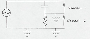
One side of both scope leads is grounded, and one side of the signal generator is grounded. This prevents you from hooking up the naive circuit below to show the 90° phase shift.

You can "fake" the situation by using a small resistor (1000W) as shown below.

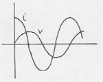
The voltage across the resistor alone shows the phase of the current through the capacitor. The voltage across both is the voltage across the capacitor -- mostly, if R<< Xc. Then these two voltages are almost
90° out of phase. For a capacitor, then, you want to use a low frequency so Xc is large.- In the similar circuit with an inductor you would use an high frequency so XL is large.
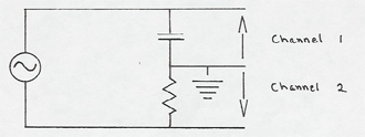
But the simplest way of demonstrating the same phase shift is use a two prong adaptor on the plug of the signal generator. Then the signal generator ground is floating, and the circuit can be hooked up as below.

You are reading the voltages across the resistor and capacitor in the opposite directions, so press the invert button on channel 2 of the scope to show properly that the voltage lags the current in a capacitor.

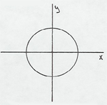
Adjust the two signals to have the same amplitude, and then turn the sweep rate knob counter-clockwise to the X-Y position to display the 90° phase shift in the form of a perfect circle.

The similar situation with an inductor is well shown with L = 50 mH and R = l0K.
